
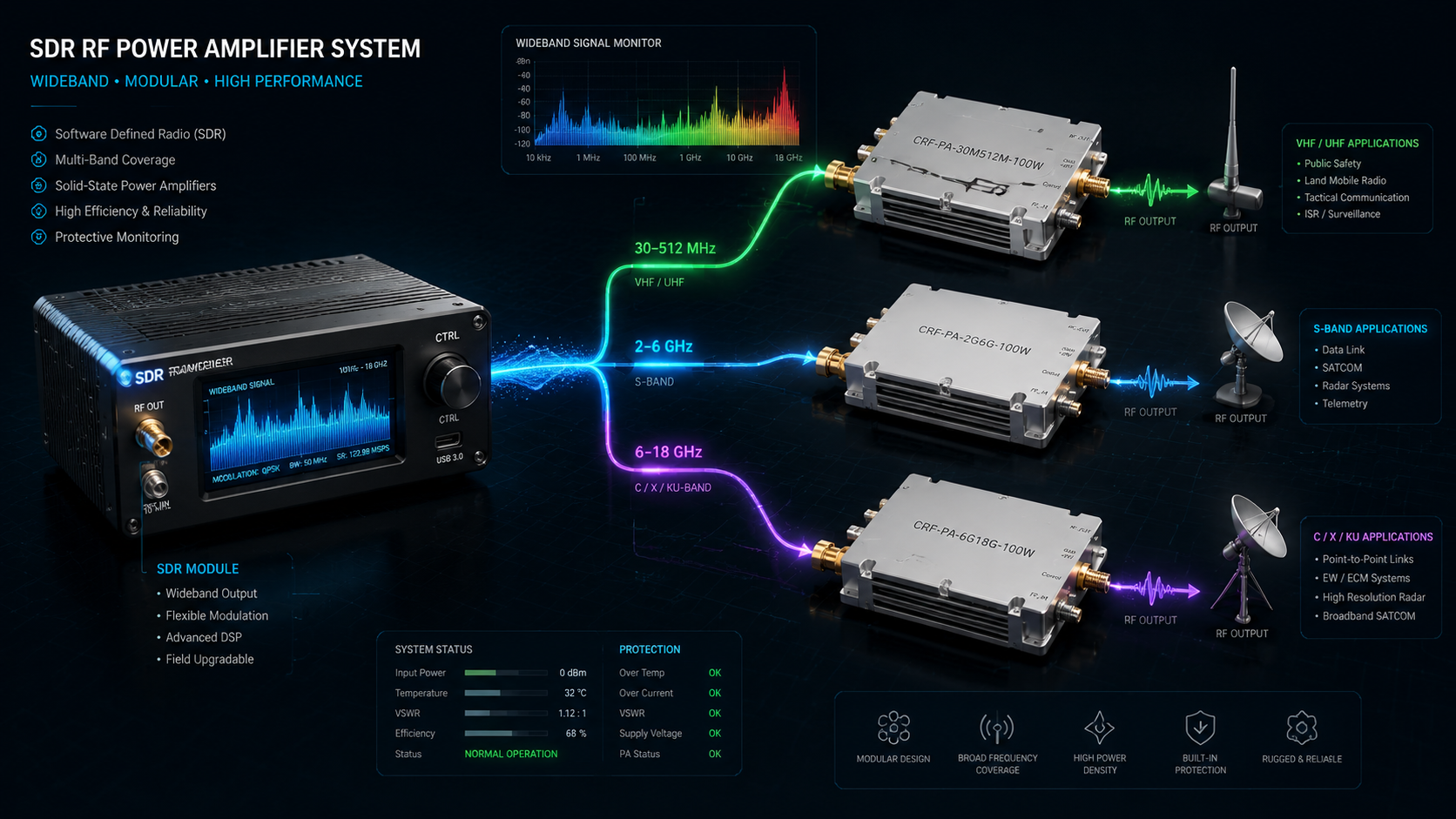
The search term SDR RF power amplifier chain reflects a real systems problem: engineers can generate flexible signals quickly, but turning that signal into a stable, usable transmission path requires careful matching across the amplifier stage, output architecture, cooling, monitoring, and load condition. Many integration delays happen because the chain is defined backward, starting from a desired antenna result instead of from the full path.
CorelixRF’s RF signal transmission solutions page provides a useful public framework. It describes the project as a coordinated path from SDR or source, through CW RF amplification, into an antenna or load, with system integration requirements such as DC input, cooling, mounting, cables, connectors, monitoring, and control. That is exactly how an SDR amplifier article should be structured.
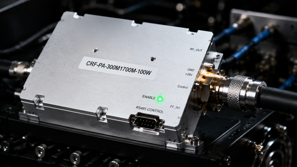
An SDR Is Flexible, but the Amplifier Still Has to Be Band-Matched
One of the clearest statements on the CorelixRF signal transmission page is that a wide SDR source does not mean one amplifier can cover the entire planned range at the required power. This point deserves emphasis because it aligns directly with search intent. Buyers looking for an SDR RF amplifier integration path are usually trying to avoid a mismatch between source flexibility and amplifier reality.
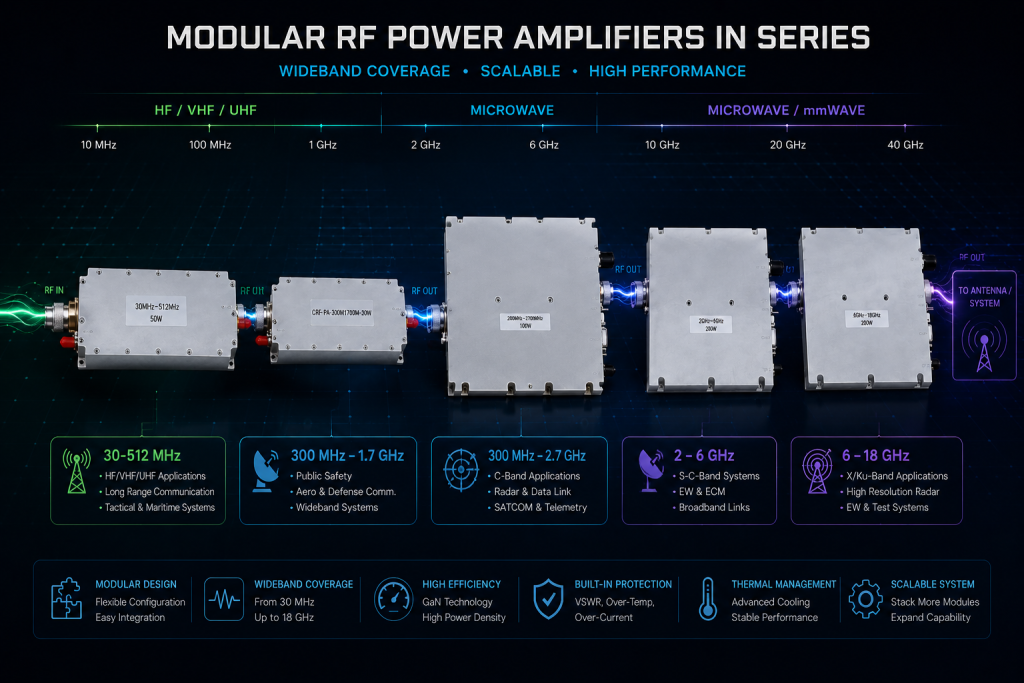
For example, CorelixRF publicly organizes practical band paths through 30-512 MHz RF power amplifiers, 300-1700 MHz broadband amplifiers, 2-6 GHz RF power amplifiers, and 6-18 GHz microwave amplifiers.
That band-based structure is more useful than the idea of a universal high-power SDR amplifier.
Start with the Signal Source Layer
The signal source layer defines more than frequency coverage. It also influences output level, waveform behavior, switching expectations, and how the rest of the chain must be controlled. CorelixRF’s transmission page references SDR source modules and notes that source flexibility is valuable because it makes wider system matching possible across downstream amplifier choices.
In planning terms, the source review should answer:
- What is the real operating frequency range?
- Is the project CW, sweep, hopping, or waveform-driven?
- What output level is available from the source?
- Does the chain require remote coordination between source and amplifier?
Without those answers, amplifier selection becomes guesswork.
Then Match the CW Amplifier Layer
The amplifier layer raises the source to the required output power, but it also introduces thermal, monitoring, and protection considerations. CorelixRF’s example architecture mentions RS485 monitoring, enable/disable control, and protection-related behaviors in the wider system context. That is exactly the level of detail that matters to system buyers.
When planning the amplifier stage, define:
- Band-matched frequency coverage
- Target RF output power
- Gain relative to source level
- Cooling method
- Control or monitoring needs
- Mechanical format for the installation
If the system is moving toward unusual packaging or mixed hardware, a custom RF development path may be more appropriate than forcing a standard product to behave like a custom subsystem.
The Output Path Deserves Equal Attention
Many projects spend too much time on source and amplifier selection, then treat the output path as a late detail. That is risky. CorelixRF’s transmission page repeatedly references antenna or load condition, VSWR concerns, cable loss, connector path, and power handling. Those are not minor implementation notes. They determine whether the SDR amplifier chain is stable in real use.
A practical chain review should include:
- Antenna type or dummy-load behavior
- Cable and connector losses
- Mismatch risk
- Whether the system is for bench validation or deployed transmission
If the project includes EMC-style bench work, the related EMC & laboratory systems page is a natural adjacent reference.
Integration and Monitoring Turn Parts into a System
The strongest distinction between a component article and a systems article is the integration layer. CorelixRF’s signal transmission page explicitly includes DC input, cooling, mounting, monitoring, control interface, and enclosure fit. That is useful because an SDR amplifier chain is usually judged by operational stability, not only by RF output.
For buyers, this means the engineering request should describe:
- Installation environment
- Power supply constraints
- Airflow or cooling assumptions
- Control method
- Documentation or validation needs
That information also maps well to the fields on the CorelixRF contact page, which asks for frequency range, output power, cooling requirement, connector preference, control interface, and application stage.
A Better Buying Framework for SDR Chains
The best way to evaluate an SDR RF chain is to think in layers:
- Source capability
- Band-matched amplifier path
- Output architecture
- Integration and monitoring
- Validation before deployment
That framework is simple, but it prevents one of the most common mistakes in RF integration: assuming the most flexible source can compensate for an underdefined power stage.
FAQ
Can one SDR RF power amplifier cover every frequency the source can generate?
Usually not. The source may be wideband, but the amplifier still needs to be matched to the actual operating band and power target.
Why should the antenna or load be reviewed early?
Because VSWR, connector limits, cable loss, and power handling all affect stability and reliability in the final chain.
When is a custom RF system path better than a standard amplifier purchase?
A custom path is better when the project needs coordinated source, amplifier, output, enclosure, interface, and monitoring decisions rather than a standalone module.
What information should be sent for engineering review?
Send frequency range, output power target, waveform or mode, connector preference, cooling method, control needs, and a brief description of the output path.