
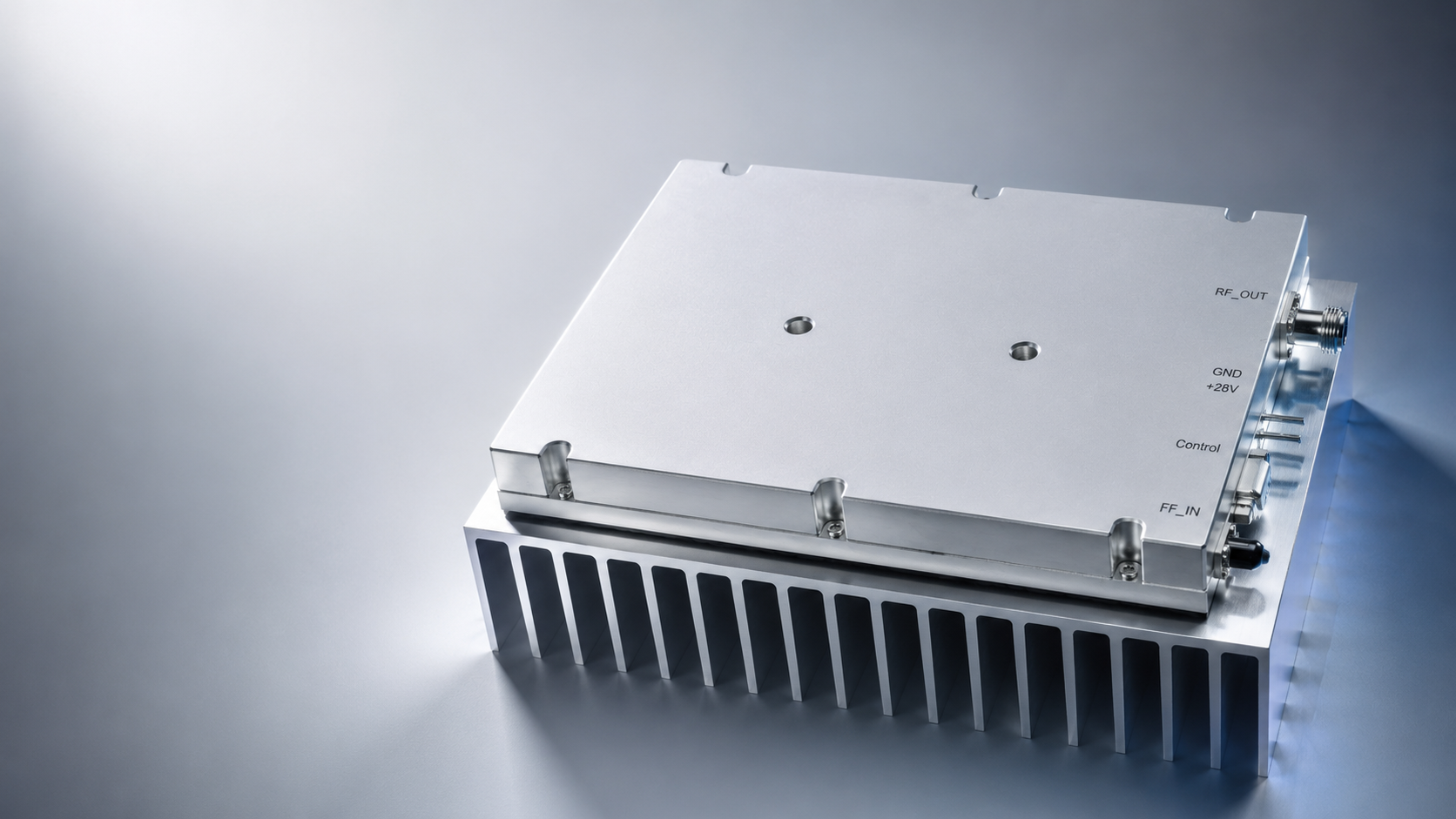
RF systems operating in the 860-930 MHz region need an amplifier choice that reflects the actual frequency plan, required load power, signal format, and installation environment. The CRF-DS-PA860M930M-150W is a 150 W RF power amplifier specified for the 860-930 MHz range. It gives system designers a focused option for applications that require amplification in this upper-UHF band without treating the amplifier as an isolated black box.
An effective selection process begins with the complete RF path. The desired result may be a controlled laboratory test level, reliable power at a remote load, or an integration-ready transmit subsystem. Each goal creates different requirements for duty cycle, thermal management, filtering, monitoring, mechanical packaging, and commissioning. The following guidance helps teams prepare those requirements without assuming features that must instead be verified in the current product documentation.
Translate the Frequency Plan into Requirements
The stated 860-930 MHz range should be compared with every planned operating condition. Include nominal channels, allowed frequency movement, calibration points, test sweeps, and any future expansion that is already known. The most useful frequency plan identifies not only the central operating point but also the low and high frequencies that the system must support in normal service.
This matters because a 150 W amplifier is part of a chain whose other components may have narrower limits. Cables, filters, circulators, couplers, antennas, loads, and switches should all be evaluated over the same frequency range. A component that performs well at one end of the band but not the other can limit the system more than the amplifier itself.
Define Useful Power at the Point of Use
The CRF-DS-PA860M930M-150W has a 150 W output-power designation. Whether that satisfies the application depends on where power is measured. A short bench cable and a long transmission path do not present the same loss budget. Build a power budget that starts at the load and works back through all planned components. Include expected cable loss at 860-930 MHz, filter insertion loss, coupler loss, switching loss, and a realistic allowance for connectors and installation variation.
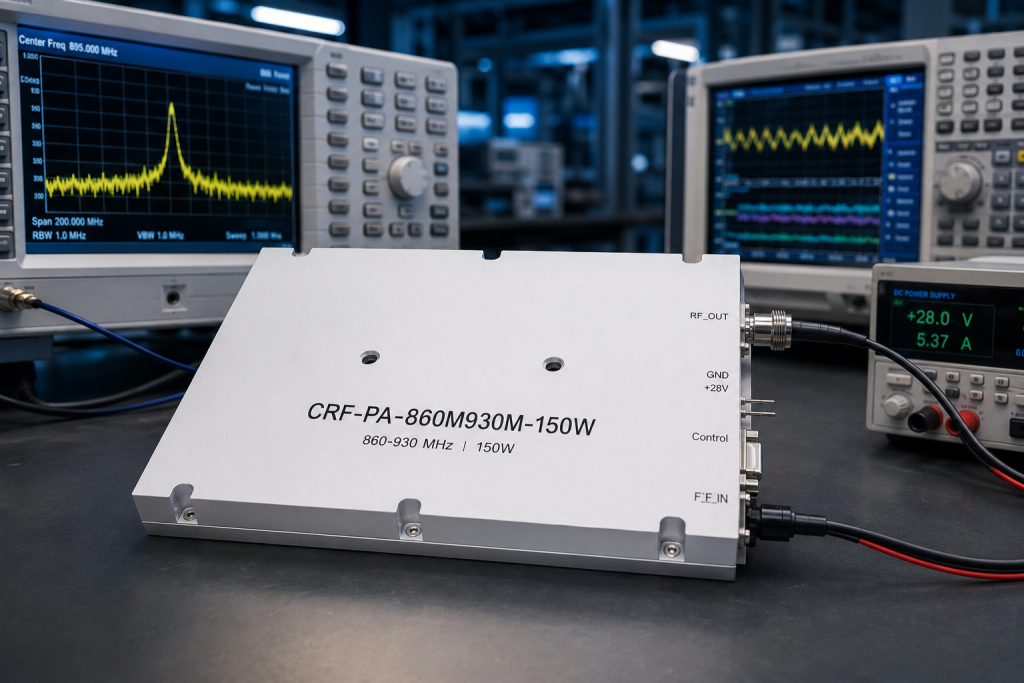
Available gain configurations are 48 dB, 50 dB, and 52 dB, allowing the input-drive plan to be matched to the selected source and control arrangement. The DC operating range is 24-32 V, with specified current options of 22 A and 27 A. Review the supply, wiring, protective devices, and distribution voltage drop against the selected configuration. RF output power alone is not an adequate basis for a DC power design.
The source drive budget is just as important. Determine how much controlled RF drive is available from the exciter or generator, how it varies across the operating band, and how it behaves with the selected modulation. Use the amplifier documentation to verify input requirements rather than assigning a drive level by rule of thumb. In a repeatable system, the drive-control method should be defined alongside the output target.
Consider the Waveform and Duty Cycle
Average output power, peak behavior, modulation characteristics, and operating duty cycle affect the demands placed on every part of an RF chain. A brief bench measurement at a favorable condition does not establish that an installation will operate reliably during a sustained test or a demanding transmission sequence. State the waveform and duty cycle in the engineering requirement, then use them in the thermal and power-supply design review.
Do not assume that a reading from one instrument tells the whole story. Select suitable measurement methods for the signal type, and agree on how forward power, reflected power, spectral performance, and temperature will be evaluated. The applicable limits should come from the system requirements and test plan.
Protect the Amplifier with Good RF Interfaces
At 150 W, interface quality deserves deliberate attention. Use cables, connectors, loads, and accessories rated for the operating frequency and expected power. Verify the impedance behavior of the source and load. A poor load condition can produce reflected power that affects output stability and creates avoidable stress elsewhere in the RF chain.
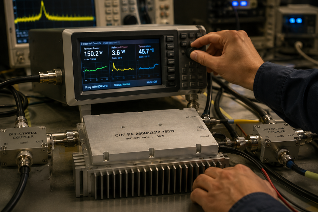
A directional coupler can be useful for observing forward and reflected power during development and commissioning. Appropriate filtering may also be required by the signal plan or the test environment. Whether filters are placed before or after the amplifier should be decided from the actual source spectrum, desired output spectrum, power capability, and insertion-loss budget. There is no single filter arrangement that suits every 860-930 MHz system.
Plan Cooling, Power, and Enclosure Integration Together
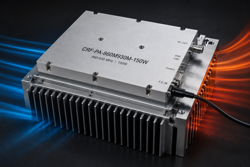
An RF amplifier delivering substantial output power requires a credible heat-removal strategy. The 150 W RF output alone does not describe the thermal load, so obtain the relevant electrical and mechanical data for the CRF-DS-PA860M930M-150W before finalizing the enclosure. Consider the expected ambient temperature, airflow, mounting surfaces, nearby heat sources, cable routing, and space for inspection.
The specified enclosure dimensions are 200 x 158 x 25 mm, and the unit requires an external heat sink. Design the mounting and thermal interface as part of the equipment architecture. A heat sink that is too small, poorly coupled, or isolated from airflow can undermine an otherwise correct RF design. Verify temperatures after the whole enclosure reaches equilibrium under a representative operating cycle.
The DC power source and distribution should be reviewed as a separate but related design topic. Confirm the supply requirements, cable sizing, grounding approach, and start-up behavior from the product documentation. Treat power wiring and RF wiring as parts of one integrated layout, with attention to service access and repeatable assembly.
Create a Practical Commissioning Process
Commissioning should be controlled and recorded. Begin with a suitable test load or validated system load. Apply reduced input drive, confirm the intended frequency, then increase power according to the approved procedure. Record input conditions, forward and reflected power, temperatures, supply behavior, and the configuration of any filters or switching equipment. Perform checks at representative points across 860-930 MHz, not only at one convenient frequency.
Optional VCO and RS485 control can be specified when the system needs a local source option or serial supervision. Confirm option selection before mechanical and electrical interfaces are frozen. Built-in protection functions are also specified; the system operating procedure should state how a protection event is recognized, what action follows, and how operation is restored according to the current documentation.
If the installation will be operated by different teams, capture these steps in a concise operating procedure. Define which indicators are checked before RF is enabled, what observations require reduced drive or shutdown, and how configuration changes are documented. These simple controls make fault diagnosis faster and help preserve comparable data over time.
Information to Include in an RFQ
A complete request for the CRF-DS-PA860M930M-150W should include the required operating frequencies, desired output at the load, signal type, modulation bandwidth, duty cycle, source capability, cooling environment, physical constraints, power-supply details, and required control or monitoring interfaces. Include any test, regulatory, or system-level constraints that affect the installation. Ask for the current datasheet and verify all published values before releasing drawings or procurement documents.
This approach keeps the discussion focused on observable requirements. It also avoids creating expectations about connector types, gain, protection behavior, dimensions, or auxiliary interfaces that have not been confirmed for the selected configuration.
FAQ
What band is covered by this RF power amplifier?
The CRF-DS-PA860M930M-150W is specified for 860-930 MHz. Verify that the intended channels and operating tolerances remain inside this band.
Does 150 W account for losses after the amplifier?
No. Losses in cables, filters, couplers, switches, and other components must be included when calculating power at the load.
Can I use the amplifier for continuous operation?
The acceptable operating profile depends on the approved product documentation, signal conditions, installation, and cooling arrangement. Review these factors for the actual duty cycle.
Which measurements should be made during commissioning?
At minimum, document frequency, source drive, forward power, reflected power, DC behavior, and temperatures using an appropriate test setup.
What details should I provide for a configuration review?
Provide your frequency plan, required output level, waveform, duty cycle, load characteristics, cooling conditions, and mechanical and electrical interfaces.
Request an 860-930 MHz RF Amplifier Configuration Review from CorelixRF