
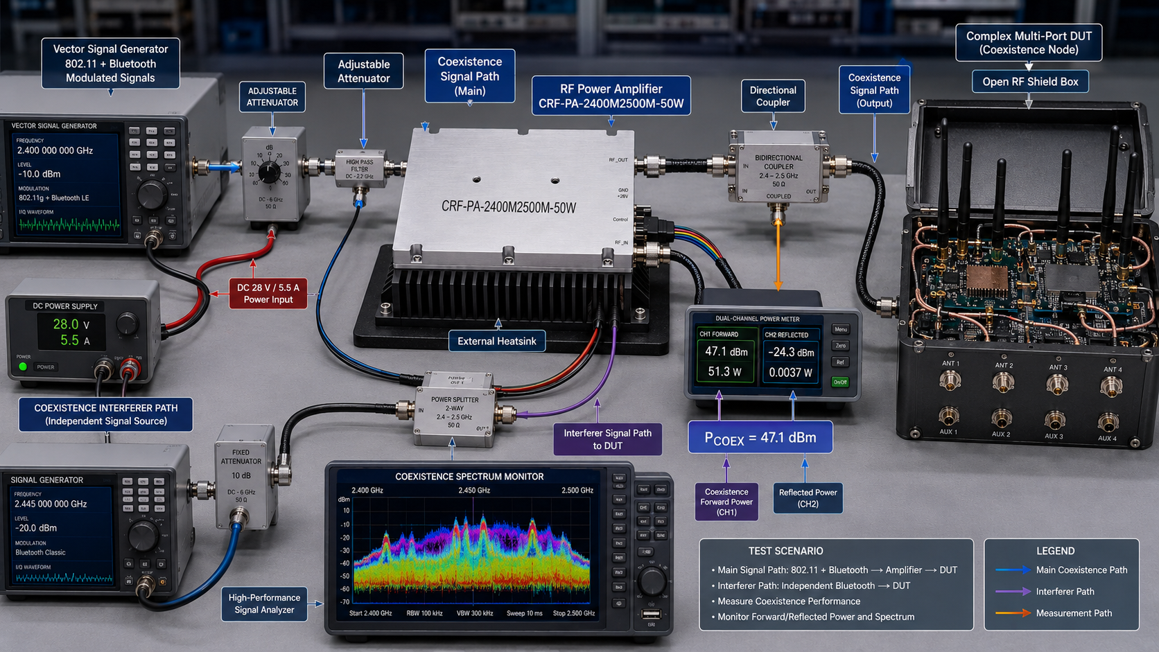
The 2.4 GHz region is familiar because it appears in many wireless ecosystems, but an RF power amplifier for 2400 to 2500 MHz should be specified with the same discipline used for any microwave power block. Output class, gain, DC supply, cooling, connector integration, duty cycle, and load behavior all influence whether a bench or embedded system is stable and repeatable. Selecting only by a nominal “2.4 GHz amplifier” description can leave important engineering questions unanswered.
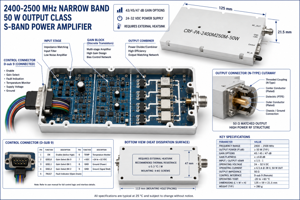
The CRF-DS-PA2400M2500M-50W is a narrowband solid-state RF power amplifier covering 2400 to 2500 MHz in the 50 W output class. It offers documented gain options of 43 dB, 45 dB, and 47 dB, operates from a 24 to 32 V supply range, and uses an external heatsink arrangement. Its compact dimensions of 125 by 59 by 21.5 mm can support space-conscious integration, provided the RF, DC, mechanical, and cooling interfaces are considered together.
DEFINE THE S-BAND TEST OBJECTIVE
Begin with the outcome the amplifier must support. A microwave component test may require a controlled CW signal at several frequencies. A wireless stress or coexistence bench may need a modulated source with carefully managed level. A subsystem integration project may be more concerned with compact packaging, repeatability, and fault response. These are different jobs even when they occupy the same 2400 to 2500 MHz band.
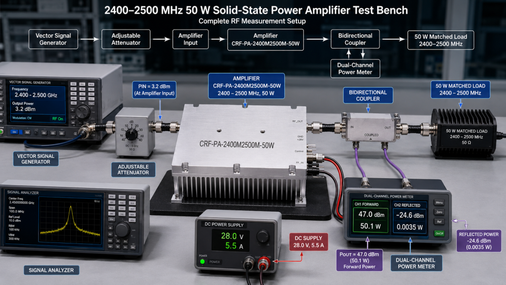
Write a frequency-and-level table before selecting the chain. Include source output, amplifier input, target amplifier output, cables, attenuators, couplers, filters, and the expected level at the device under test. This simple exercise reveals whether the available source control is adequate and whether the power meter, load, switch, and fixture are rated for their real operating conditions. It also avoids treating 50 W at the amplifier port as 50 W everywhere in the system.
MATCH THE GAIN TO THE AVAILABLE DRIVE
The listed 43 dB, 45 dB, and 47 dB gain choices give system designers a way to match the power stage to an existing source or driver. Gain should be chosen with both maximum and minimum test level in mind. A signal generator may have enough output to drive a high-gain stage, but without controlled attenuation the system can become difficult to adjust precisely. Conversely, an overly conservative gain choice can leave the desired output out of reach after cable and fixture losses.
Estimate the required RF drive, then include enough range for calibration and production variation. Keep an adjustable attenuator or controlled level element where the test process benefits from repeatable stepping. When modulation is present, consider its crest factor and the desired operating margin. Exact waveform limits should be reviewed with the amplifier supplier rather than assumed from a CW output class.
PLAN THE 24-32 V POWER PATH
The amplifier’s stated DC range is 24 to 32 V. Listed current figures are 5 A and 6 A for the relevant versions. These numbers help define the supply capacity, fuse or circuit protection, wiring gauge, and distribution architecture. A compact amplifier can still experience poor performance if it receives an unstable or sagging voltage under load.
Keep the DC path short and well characterized, especially when the unit is installed away from the supply. Verify voltage at the amplifier during the anticipated RF duty cycle. In racks and automated stations, document the supply enable sequence and ensure that the interlocks used by the broader system are compatible with the amplifier’s intended operation. Good DC integration makes troubleshooting much faster when output behavior differs from a baseline measurement.
DESIGN THE THERMAL INTERFACE BEFORE THE ENCLOSURE
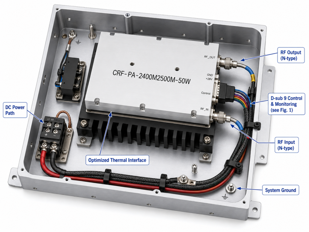
The compact 125 by 59 by 21.5 mm package requires an external heatsink. The mechanical design must therefore provide a reliable thermal interface, adequate heatsink area, and airflow or conduction appropriate for the expected duty cycle. Do not assume that a small housing means a small heat-management task. Heat must still leave the assembly while the amplifier is producing RF power.
Use flat mounting surfaces, suitable thermal interface material, and an arrangement that allows warm air to escape. If the assembly is installed near other heat sources, evaluate the combined ambient rise. Validate the actual enclosure with a representative signal and duty cycle. This is more useful than a room-temperature bench check because real installations often have different airflow and cabling constraints.
INTEGRATE THE CONTROL AND MECHANICAL INTERFACES
The model uses a D-sub 9 interface. Include the mating connector, cable routing, strain relief, grounding approach, and service access in the physical design. Interface details should be confirmed from the supplied documentation before wiring. A clean harness layout reduces accidental disconnection and makes fault diagnosis more straightforward.
Thermal protection is listed for this amplifier. It should be viewed as a protective layer, not an alternative to sound cooling. Establish how the wider system should react if an over-temperature condition is observed: reduce or remove RF drive, check airflow and mounting, inspect DC supply conditions, and allow a controlled recovery. A documented operator procedure is valuable in both lab and production environments.
USE SAFE RF PRACTICES AT 50 W
Fifty watts can damage unsuitable components and create misleading results when impedance mismatch is ignored. Select connectors, cables, attenuators, couplers, switches, and loads that are rated for the expected frequency and power. Inspect adapters carefully; a convenient adapter may have a lower power rating or poorer match than the main test hardware. Where the device under test can present a variable impedance, use appropriate isolation, monitoring, and operating limits.
For a new setup, start at low drive, confirm the signal path with measurement equipment, then increase level in controlled steps. Record baseline forward power, reflected power where available, supply voltage, current, and temperature. This method makes it easier to distinguish a source-level issue from a cable fault, thermal limitation, or load problem.
WHERE A 2400-2500 MHZ 50 W AMPLIFIER FITS
This narrowband S-band amplifier can be considered for microwave component characterization, wireless system test, RF subsystem development, and integration work that needs a defined 2.4 to 2.5 GHz power stage. The narrowband range is useful when the required frequencies are known and the design benefits from focusing on that application window.
Final suitability should be based on the actual signal type, bandwidth, duty cycle, expected mismatch, environmental conditions, and installation constraints. Avoid inferring unlisted certifications, availability, or application outcomes. A concise technical review of the system requirements is the best way to establish a reliable configuration.
FAQ
What frequency range is specified for this amplifier?
The stated range is 2400 to 2500 MHz. Confirm that the full operating plan remains within that range.
What is the output-power class?
This model is specified in the 50 W output-power class. Downstream components must be selected for the real power and frequency they will handle.
Which gain options are listed?
The listed gain options are 43 dB, 45 dB, and 47 dB. Choose the option that matches the source level and needed adjustment range.
What DC input is required?
The documented supply range is 24 to 32 V. Listed current figures are 5 A and 6 A for the relevant versions.
How is the amplifier cooled?
An external heatsink is required. Validate the complete installed thermal path at the intended duty cycle.
CONTACT CORELIXRF TO DISCUSS A 2400-2500 MHZ RF POWER AMPLIFIER PROJECT