
Narrowband UHF systems are judged by transmitted-signal consistency, not peak power alone. A 400-440 MHz RF power amplifier must fit its operating band, deliver useful power without compromising the preceding exciter, and remain practical to integrate. The CRF-DS-PA400M440M-100W is a 100 W amplifier designed for operation across the 400-440 MHz range. It is a starting point for engineers who need a focused UHF amplification stage.
Why a Defined 400-440 MHz Band Matters
A narrow operating band gives a design team a clearer set of tradeoffs than an amplifier intended to cover many octaves. When the required signal falls within 400-440 MHz, selecting an amplifier whose stated band matches that requirement helps keep the RF chain focused on the actual application. It also reduces pressure to accept a broad-band solution simply because it is available.
Frequency should be checked as a range, not as a single center point. A program that initially plans to operate near the middle of the UHF band may later need channels near either end. Confirm that the intended channels, modulation bandwidth, test tolerances, and any frequency-agility requirements stay inside 400-440 MHz. It is equally important to define whether the stated operating frequencies are continuous, stepped, or used only during a laboratory qualification sequence.
Power Is a System Requirement
The 100 W rating of the CRF-DS-PA400M440M-100W is the starting point for a power-budget discussion. Engineers should work backward from the required power at the load, accounting for cable loss, connectors, filters, switching hardware, couplers, and any antenna or test-fixture losses. A system can meet a nominal 100 W output at the amplifier while delivering materially less power at the point where it matters.
For input-drive planning, the available gain configurations are 46 dB, 48 dB, and 50 dB. The appropriate choice should be selected against the actual source level and required output control range. The amplifier operates from a 24-32 V DC supply; specified current options are 16 A and 20 A. These values should be used when reviewing supply capacity, distribution losses, wiring, fusing, and the startup sequence rather than inferring supply needs from RF output alone.
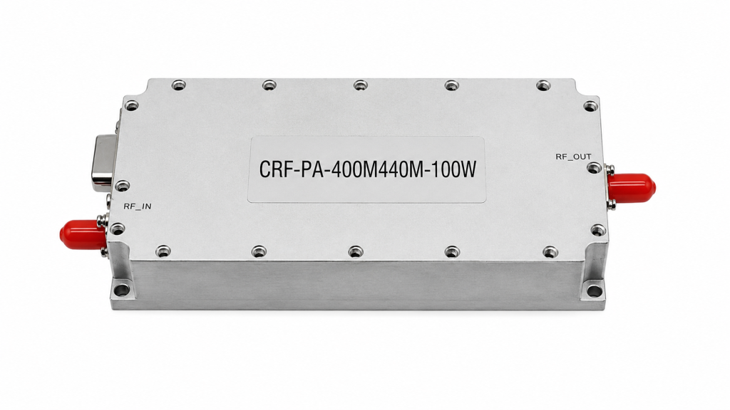
The input source also needs attention. Determine the available drive level from the signal generator, modem, exciter, or preceding gain stage. Confirm the desired output level for the selected waveform and operating duty cycle before assuming that a single drive setting will be appropriate for every mode. Good integration practice includes a controlled startup sequence and an agreed method for reducing drive when the downstream path is unavailable or out of tolerance.
Build the RF Chain Around the Amplifier
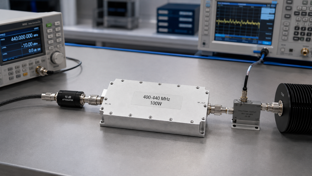
An amplifier should be treated as one element in a matched RF path. Before finalizing the layout, document the source, amplifier, filtering, monitoring, transmission line, load, and any switching elements. This simple block diagram often exposes missing components: an input attenuator for drive control, a directional coupler for forward and reflected-power observation, or a filter required by the system spectral plan.
Impedance matching must be considered at every interface. A poor match can increase reflected energy, make output readings unstable, and complicate troubleshooting. Use components rated for the operating frequency and expected RF power, including suitable margin for the operating conditions. If a load can change during operation, define the behavior that the complete system should follow when reflected power rises.
The placement of filters depends on the application. An input filter may help control unwanted content produced upstream, while an output filter may be appropriate when the system must manage harmonic or spurious emissions. Filter selection should be based on measurement and the applicable system requirements, not on a generic assumption that every installation needs the same topology.
Thermal Planning Is Part of RF Performance
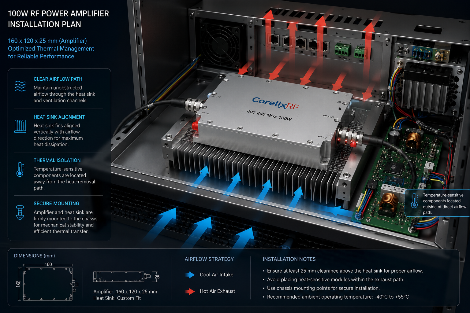
A 100 W RF output stage generates heat that has to leave the enclosure. Output power is not the same as DC input power, so thermal design requires the actual amplifier documentation and the operating profile. Ambient temperature, available airflow, enclosure volume, mounting orientation, and adjacent heat sources can all affect the final result.
The amplifier outline is 160 x 120 x 25 mm and it requires an external heat sink. Treat that heat sink as an engineered assembly, not merely a mounting surface. Its material, flatness, thermal interface, airflow, and connection to the larger enclosure need to support the intended duty cycle. Allow service clearance for both the RF connections and the heat-removal path.
Begin with the physical installation plan. Provide a clear air path where the product documentation calls for it, avoid blocking cooling surfaces, and keep temperature-sensitive components away from the hottest area. In a rack or equipment cabinet, consider the heat contributed by every RF and power component rather than assessing the amplifier by itself. Verify the result with measurements during a representative duty cycle, especially when the intended service involves long transmissions or repeated test sequences.
Control and Monitoring Make Commissioning Easier
The quickest path to a dependable RF subsystem is measurable behavior. Establish a commissioning procedure that records operating frequency, commanded output level, input drive, forward power, reflected power, enclosure temperature, and DC supply behavior. The exact available monitoring and control connections should be confirmed in the CRF-DS-PA400M440M-100W datasheet before the interface is designed.
Optional VCO and RS485 control are available for configurations that need a locally controlled source function or a serial supervisory interface. Confirm which option is needed before finalizing the panel and harness design. The amplifier also includes protection functions; define how those protections are indicated and handled in the host system, using the current specification for the exact behavior and reset procedure.
For production or fielded equipment, decide in advance who can enable RF power, how faults are indicated, and what condition requires a shutdown. Interlocks and monitoring should match the risk of the complete system. A bench used by trained engineers may need a different workflow from a remotely operated installation.
Questions to Ask Before Ordering
The best procurement request is specific. State the 400-440 MHz operating frequencies, required output level at the load, waveform and duty cycle, source drive information, desired mechanical configuration, cooling environment, power-supply constraints, and control or monitoring needs. Include any test standards, deployment restrictions, and delivery documentation requirements. These details let an amplifier supplier assess whether the standard unit is appropriate or whether the overall RF chain needs adaptation.
For the CRF-DS-PA400M440M-100W, also request the current datasheet and confirm all interface, gain, power-supply, protection, environmental, and mechanical details for the intended configuration. Avoid designing to an assumed connector type, assumed gain, or assumed fault response.
Commissioning Checklist
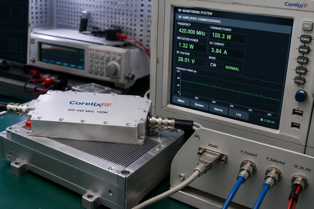
Start with a verified load or test fixture rated for the expected frequency and power. Bring the RF chain up at reduced drive, observe the relevant measurements, and increase output only under the approved test procedure. Record baseline data at representative frequencies across the 400-440 MHz band. Repeat checks after the enclosure has reached its expected operating temperature. If a result changes unexpectedly, stop and investigate the source, load, cabling, cooling path, and measurement setup before continuing.
FAQ
What frequency range does this amplifier cover?
The CRF-DS-PA400M440M-100W is specified for 400-440 MHz operation. Confirm that every planned channel and tolerance falls within that range.
Is 100 W the power delivered at the antenna?
No. The amplifier rating is not automatically the power at the antenna or another remote load. Account for losses and verify the actual delivered power in the installed RF path.
Can it be used with any signal generator?
The source must provide appropriate drive and signal quality for the required operating point. Confirm input requirements from the current datasheet before connecting equipment.
What should be checked during installation?
Check the RF match, component power ratings, cooling arrangement, supply requirements, measurement plan, and fault-handling procedure for the complete system.
How can I request a configuration review?
Provide your frequency plan, output target, waveform, duty cycle, installation constraints, and interface requirements so the application can be reviewed.
Discuss Your 400-440 MHz RF Amplifier Project with CorelixRF