
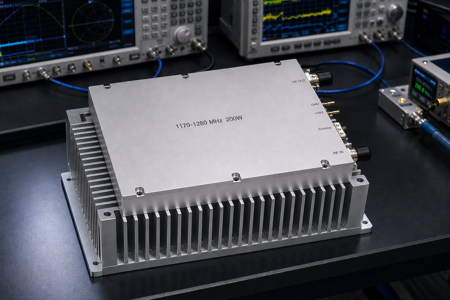
L-band power stages are often selected by a frequency label and a peak-power figure, then discovered to be difficult to integrate. A useful specification needs to connect the required signal band, output level, gain, supply arrangement, thermal path, and protection behavior. This is particularly important for GNSS-adjacent development, telemetry benches, avionics test setups, and other L-band test environments where a driven amplifier must remain predictable during repeated sweeps and changing loads.
The CRF-DS-PA1170M1280M-200-V1.0 is a narrowband solid-state RF power amplifier intended for the 1170 to 1280 MHz range. Its stated 200 W output class makes it relevant when a laboratory or system integrator needs more than a low-level driver but does not want to assume that all L-band amplifiers have the same electrical and mechanical requirements. The right question is not simply whether an amplifier covers L-band. It is whether its documented operating window fits the source, load, enclosure, and test procedure.
START WITH THE ACTUAL FREQUENCY WINDOW
The first filter is the required operating band. A 1170 to 1280 MHz amplifier should be evaluated against the full frequency plan, including edge frequencies, calibration points, and any intended modulation bandwidth. Engineers should not replace a stated narrowband range with a generic “L-band” assumption. If the application requires operation outside this interval, a different frequency plan or a custom review is appropriate.
For a test chain, map the intended source frequencies and expected output level at each point. Allow for cable loss, couplers, switches, attenuators, and fixtures between the amplifier and the device under test. This prevents a common error: specifying 200 W at the amplifier output but overlooking the level actually delivered to the load. It also helps determine whether a directional coupler and power sensor are needed for closed-loop test control.
USE GAIN AS AN INTEGRATION PARAMETER
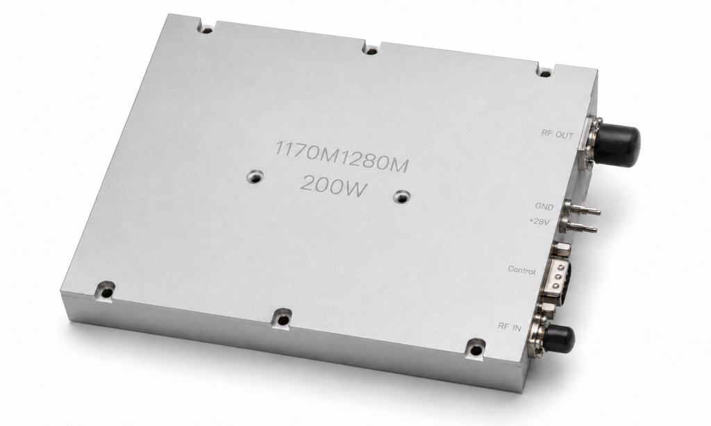
The listed gain options for this model are 49 dB, 51 dB, and 53 dB. Gain is not an abstract performance score; it sets the RF drive required from the preceding stage. A high-gain 200 W amplifier can reach a substantial output level from a modest source, so the upstream signal path should have adequate level control and protection against accidental overdrive.
When comparing gain options, use the source’s maximum available output, any programmable attenuation, and the desired adjustment resolution. A bench with a signal generator and external attenuator may benefit from a gain selection that provides a comfortable adjustment range. A compact integrated system may instead prioritize a gain option that matches an existing driver. In either case, confirm the desired operating point across the full 1170 to 1280 MHz band rather than at one convenient center frequency.
POWER SUPPLY AND CURRENT PLANNING
This amplifier operates from a 24 to 32 V supply range. Published current figures are 30 A and 36 A for the corresponding versions. These values should be used to size the DC source, cabling, connectors, distribution protection, and voltage-drop budget. A supply that is nominally within range may still be unsuitable if lead resistance causes the voltage at the amplifier to fall during high-output operation.
Treat the DC path as part of the RF design. Use appropriately rated wiring, define a stable return path, and consider startup and transient behavior in the wider system. Where multiple loads share a supply, review their combined current profile. A well-sized supply with remote sensing or carefully managed wiring can make a test setup much more repeatable than a supply selected only by its headline wattage.
THERMAL DESIGN IS A SYSTEM RESPONSIBILITY
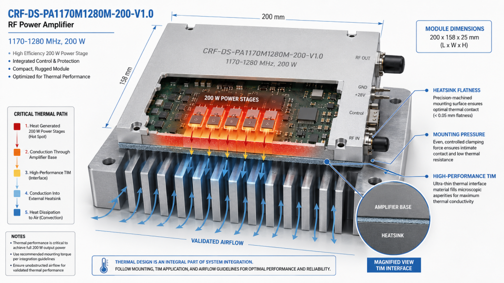
At this output class, thermal management deserves early attention. The unit dimensions are 200 by 158 by 25 mm, and the design requires an external heatsink. That is an integration requirement, not an optional accessory. The final thermal result depends on heatsink flatness, interface material, mounting pressure, airflow, enclosure temperature, duty cycle, and neighboring heat sources.
Plan the mechanical stack before finalizing an enclosure. Provide a low-resistance thermal route from the amplifier base to the external heatsink, avoid trapping hot air, and validate temperature at the intended duty cycle. Short bursts, CW use, pulsed operation, and swept tests can load the thermal system differently. If the application will operate near maximum output repeatedly, measure the installed assembly rather than relying on free-air expectations.
PROTECTION FEATURES SUPPORT ROBUST OPERATION
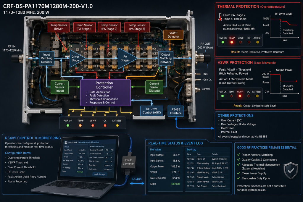
The specified protections include RS485 control, VCO-related control, thermal protection, VSWR protection, voltage protection, and current protection. These functions can make integration safer, but they do not remove the need for good RF practices. A poor match, a damaged cable, or an incorrectly rated load can still interrupt a test and may trigger protective behavior.
Build the protection plan around the complete chain. Use loads and components rated for the expected RF power, keep connectors clean and correctly torqued, and check return loss where the fixture can change. Record the expected behavior when a fault condition occurs so operators know whether to remove drive, check DC supply, investigate cooling, or inspect the load. RS485 can be useful where a system needs status or coordinated control; establish the interface convention during the design review instead of leaving it to commissioning.
APPLICATIONS THAT BENEFIT FROM A NARROWBAND 200 W STAGE
A 1170 to 1280 MHz, 200 W amplifier can fit L-band component characterization, receiver stress testing, subsystem development, telemetry-oriented test chains, and controlled radiated or conducted test configurations where the frequency plan stays inside the documented range. It can also be considered for integration projects that need a compact RF power block with defined DC and thermal requirements.
Application suitability still depends on modulation, crest factor, mismatch exposure, ambient conditions, and compliance responsibilities. Do not infer certifications, installed inventory, or a particular mission use from the frequency range alone. A technical review should translate the real waveform and load conditions into a safe operating plan.
FAQ
What frequency range does the amplifier cover?
The stated operating range is 1170 to 1280 MHz. Confirm that all required operating and test frequencies fall within this window.
What output-power class is specified?
This model is specified in the 200 W output-power class. System-level delivered power will also depend on downstream losses and load conditions.
Which gain options are available?
The listed gain options are 49 dB, 51 dB, and 53 dB. Select the option with the source level and adjustment range in mind.
What DC supply should be planned?
The documented supply range is 24 to 32 V, with listed current figures of 30 A and 36 A for the relevant versions. Size the supply and cabling for the installed system.
Does the amplifier need external cooling?
Yes. The 200 by 158 by 25 mm unit requires an external heatsink, and the final cooling solution should be validated in the actual enclosure.
CONTACT CORELIXRF FOR A 1170-1280 MHZ AMPLIFIER REVIEW