
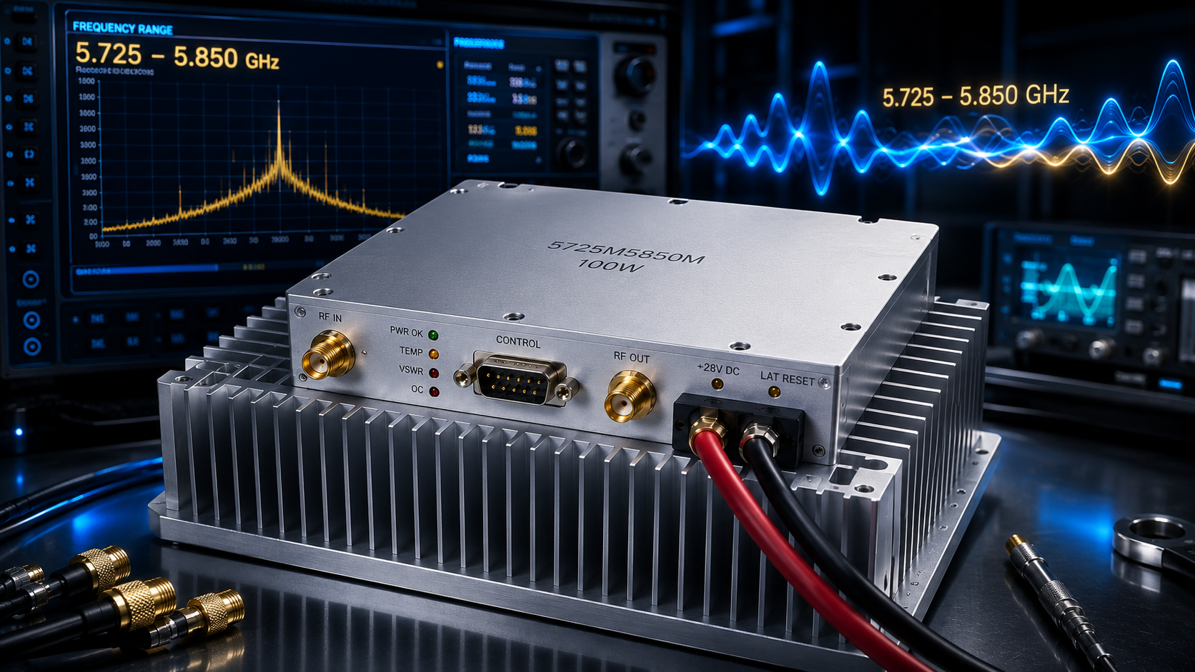
Microwave-link development often fails at the handoff between a clean laboratory source and the real RF subsystem. A source may cover the desired channel, yet it may not provide enough drive power to evaluate the downstream antenna, filter, duplexer, coupler, or receiver-protection path at a realistic level. The CRF-PA-5725M5850M-100W is a solid-state narrowband RF power amplifier designed for the 5.725 GHz to 5.850 GHz range and rated for 100 W CW output. That frequency window makes it a practical candidate when an engineering team needs a controlled C-band test signal rather than a general-purpose broadband amplifier.
The important selection question is not simply whether 100 W is sufficient. Engineers also need to confirm usable gain, source compatibility, cooling, control behavior, reflected-power conditions, and the difference between a test configuration and a deployed radio system. A narrowband amplifier is most useful when its operating range, interfaces, and protection behavior are reviewed as a complete integration package.
Why a Narrowband 5.725-5.850 GHz Amplifier Matters
The 5.725-5.850 GHz range is used in many microwave communication, RF measurement, and subsystem-development activities. For these projects, an amplifier that is specified around the intended operating band can simplify test planning. The CRF-PA-5725M5850M-100W is specified for 5.725 GHz to 5.850 GHz operation in a 50 ohm system, with 80 W minimum and 100 W typical saturated output power. Its stated gain is 46 dB minimum, 48 dB typical, and 50 dB maximum.
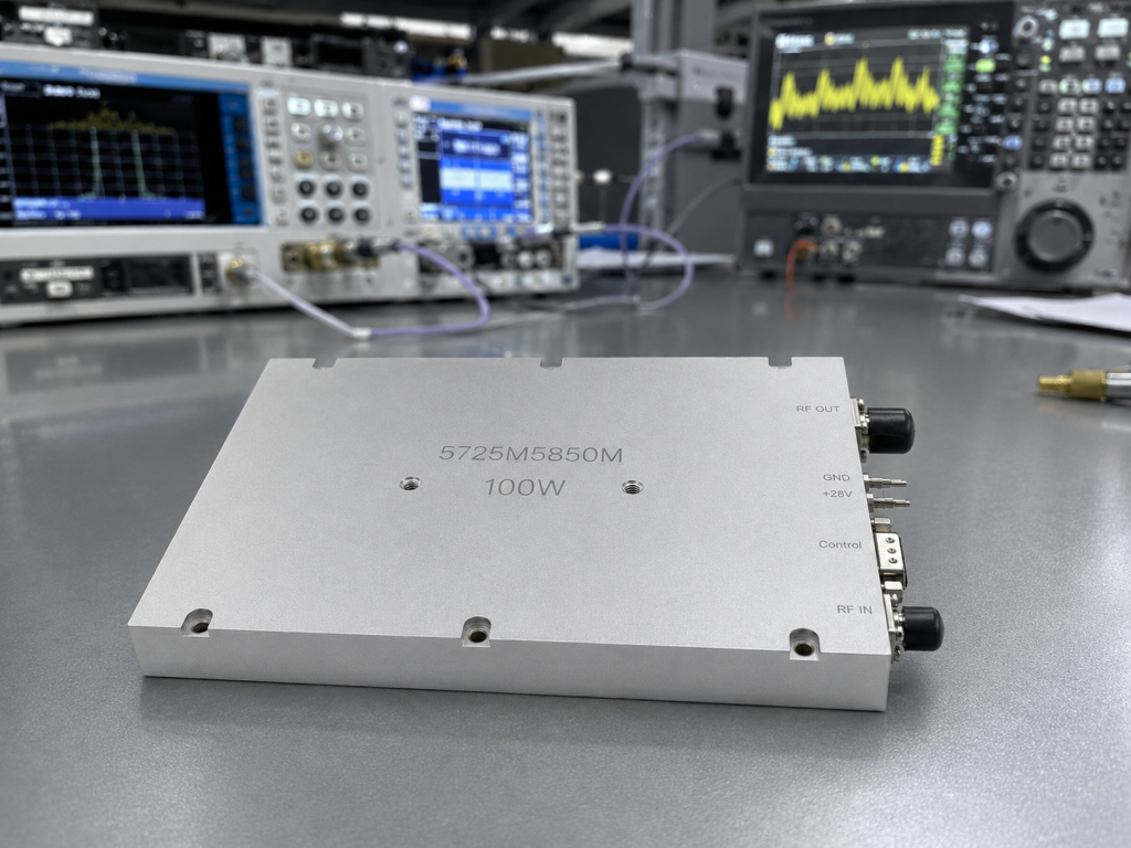
Those gain figures matter because the preceding source, modulator, or driver must be planned with adequate margin. A system should not assume that a signal generator can be connected directly to a high-power amplifier without checking input level, modulation characteristics, interconnect loss, and desired output back-off. If the test calls for linearity-sensitive waveforms, the team should determine output operating point from the project test data rather than treating saturated-power information as a linear operating guarantee.
The product supports an M version with an RF input connector and a V version with an internal VCO source. The V version is described with 10 Hz frequency stepping, a 5.650-5.900 GHz frequency-adjustment range, and a 100-300 MHz bandwidth-adjustment range. Selection between these versions should follow the source architecture. A system that already has a qualified external source may favor the M configuration, while an integrated source-and-amplifier test fixture may require review of the V configuration and its control needs.
Plan the RF Signal Chain Before Applying Power
A reliable microwave test chain starts with the source and ends with the load, but each intermediate component affects what the amplifier sees. Begin by documenting target frequency, modulation, output level, duty cycle, cable losses, and required test points. Confirm that the upstream source can be controlled safely and that the downstream assembly is rated for the expected RF power. Directional couplers, attenuators, filters, and power meters should all be selected for the operating band and expected power level.
The datasheet states SMA-KFD46 RF connectors for input and output. Connector type alone does not prove a complete assembly is ready for 100 W operation; the entire path, including adapters and cables, needs a power and frequency review. Where forward and reflected power must be observed, place the measurement method in the test plan before energizing the unit. The product documentation describes optional forward/reverse power indication, and project teams should confirm the chosen configuration and signal scaling during technical review.
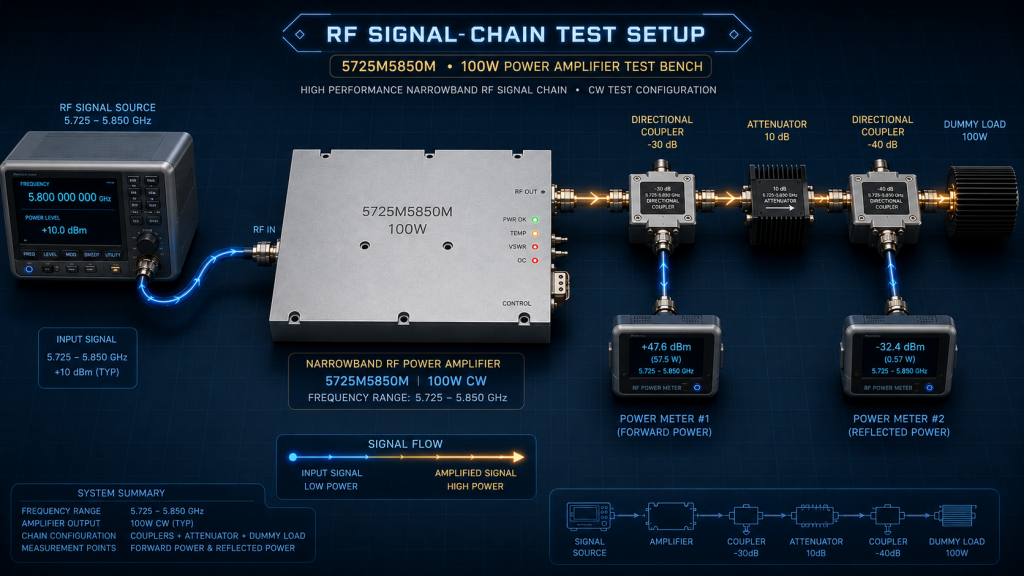
Input match is another integration detail. For the M version, the stated input VSWR is 1.5 maximum. A source with poor match, a damaged cable, or an unexpected filter response can create different conditions from a simple bench setup. Good practice is to characterize the passive chain first, use known-good terminations, and add power in controlled increments while recording forward and reflected readings.
Thermal Design Is Part of RF Performance
The amplifier uses external heat-sink cooling. Its listed mechanical size is 160 by 120 by 25 mm and its weight is 1.4 kg. These numbers help a designer allocate space, but they are not a replacement for a thermal design. The mounting surface, heat-sink flatness, interface material, airflow, enclosure temperature, and installation orientation can all influence operating temperature.
The specified operating-temperature range is -40 to +60 degrees C. In a laboratory, ambient temperature may look benign while the heat-sink interface becomes the limiting factor. In an enclosed microwave rack, neighboring supplies and RF loads can raise the local thermal environment far above room temperature. The correct approach is to use the amplifier’s stated cooling requirement as an input to thermal analysis, then validate the installed configuration with temperature monitoring under the intended RF duty cycle.
The nominal supply is +28 V DC, with a stated operating range of +24 to +32 V. Typical and maximum current are listed as 16 A and 20 A. Supply wiring, connectors, fuse strategy, and return paths should therefore be selected for the actual installation rather than only for nominal calculations. Voltage drop at the amplifier under load can affect operation, especially when a remote supply is connected through long leads.
Control, Monitoring, and Protection Review
The CRF-PA-5725M5850M-100W includes PA enable/disable control with a listed maximum switching time of 100 microseconds. The D-Sub 15-pin control interface can support RS485, alarm reset, forward/reverse RF power indicators, temperature monitoring, and PA enable depending on configuration. The documentation identifies PA on as 0 V or floating and PA off as a 3.3 V or 5 V input. Those details should be verified against the final control logic before interconnection.
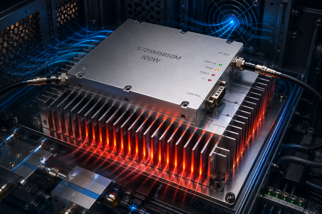
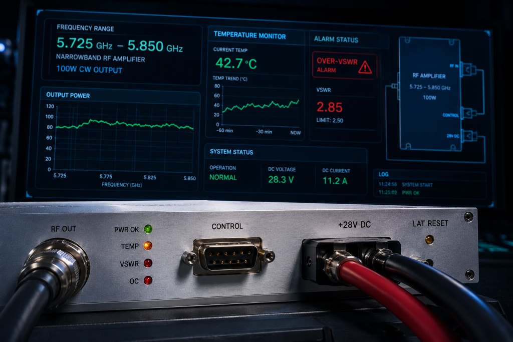
Protection behavior is valuable only when it is understood by the system integrator. The datasheet describes shutdown above 80 degrees C plus or minus 5 degrees C and automatic recovery below 70 degrees C plus or minus 5 degrees C. It also describes over-VSWR, voltage, and current alarms. Over-voltage and over-current conditions can be locked states that require reset, so an automated test system should not simply cycle RF drive and assume that the amplifier has returned to its intended state. The test procedure should log alarms, check supply conditions, inspect the load path, and use the defined reset method where applicable.
The optional temperature-monitor signal is described as 10 mV per degree C with a 0.50 V offset. When used, this can help correlate enclosure conditions with amplifier behavior. It should be treated as a diagnostic input, not as a substitute for an independent thermal validation of the assembled system.
How to Build a Meaningful Acceptance Test
An acceptance test for a narrowband microwave amplifier should reflect the project, not merely confirm that RF output exists. First, inspect the mechanical installation, cooling path, DC polarity, and all RF connections with power off. Second, confirm that the load chain is rated, matched, and instrumented. Third, apply DC power and verify control-state behavior before RF drive. Finally, increase RF level gradually while checking output power, supply current, temperature, and any available forward/reflected-power indicators.
Run frequency points across the required portion of 5.725-5.850 GHz rather than evaluating only one convenient center frequency. If the project uses an external source, record source level and cable loss at each point. If it uses the V configuration, document the selected frequency and bandwidth control conditions. Any measurement of spurious response, harmonics, or modulation quality must use the project configuration and appropriate instruments; the datasheet values are specifications, not a complete system test record.
FAQ
What frequency range is specified for this amplifier?
The CRF-PA-5725M5850M-100W is specified for 5.725 GHz to 5.850 GHz operation.
Is the 100 W value a guaranteed linear output level?
The product data lists 80 W minimum and 100 W typical saturated output power. Linear operating level depends on the waveform and required performance and should be validated in the project test setup.
Does it require an external heat sink?
Yes. The datasheet specifies external heat-sink cooling, so the installed thermal interface must be designed and tested.
Can the amplifier be used with an external RF source?
The M version is described with an RF input connector for an external source. Confirm the selected version, input level, and control requirements during project review.
What should be checked after a protection alarm?
Check temperature, RF load match, supply voltage and current, cabling, and the specified reset behavior before returning the amplifier to service.
Contact CorelixRF to discuss a 5.725-5.850 GHz narrowband RF amplifier integration or test requirement.