
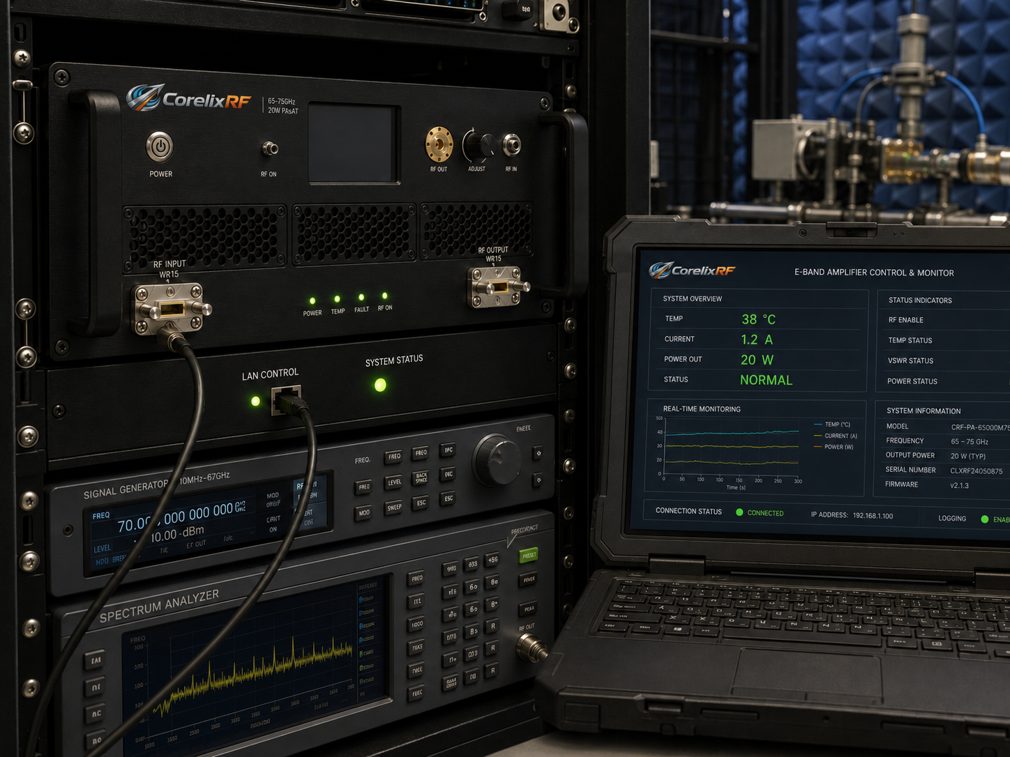
E-band and upper mmWave test platforms need amplifier hardware that treats the RF interface, cooling, control, and monitoring as part of the specification. CorelixRF CRF-PA-65000M75000M-20W is listed as a 65-75 GHz 20 W mmWave power amplifier based on GaN SSPA technology. The data sheet specifies 65 GHz to 75 GHz frequency coverage, 20 W rated RF output power, 43 dB minimum small-signal gain, WR15 front-panel input and output, RS485 / LAN control, AC 220 V ±10% supply, forced-air cooling, and a 19-inch 3U rack-mount form factor.
Why 65-75 GHz mmWave Amplifier Selection Is Different
At 65-75 GHz, the practical system is not just an amplifier and two cables. Waveguide alignment, flange quality, fixture repeatability, calibration plane, and thermal stability all affect measured performance. A mmWave power amplifier for this band should be specified together with waveguide components, sensors, test fixtures, and automation requirements.
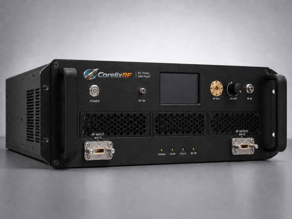
The CRF-PA-65000M75000M-20W data sheet positions the amplifier for test and measurement instrumentation, communication systems, RF interference system-level testing, and aerospace control. Its 19-inch 3U chassis and forced-air cooling make it more suitable for rack-based test environments than loose module builds. The front-panel WR15 input and output also simplify system layout when the rack interface is planned around waveguide rather than coaxial connectors.
Specifications That Matter in E-Band Test Systems
The listed frequency range is 65 GHz to 75 GHz, with 20 W rated output power. Small-signal gain is 43 dB minimum, and gain flatness is specified from -10 dB to +10 dB. Gain control range is listed up to 15 dB. Input impedance / VSWR is listed as 50 ohm with 1.5:1 typical VSWR. Harmonics are listed at -20 dBc, and spurious at -60 dBc.
Control is RS485 and LAN. That is important because many E-band RF power amplifier systems operate inside shielded areas, chamber setups, or rack environments where manual operation is inefficient. Engineers should request the final protocol, remote monitoring fields, alarm state behavior, and reset procedure during project review.
Monitoring and protection features include real-time temperature monitoring, real-time current monitoring, alarm and fault protection, over-temperature protection, over-drive protection, over-voltage protection, and VSWR protection and alarm functions. Optional forward/reverse power monitoring, input power detection, and GPIB programmable control may be available.
Integration Guidance for WR15 Amplifier Chains
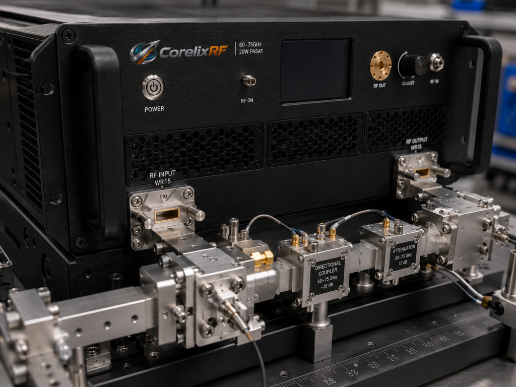
The amplifier uses WR15 for both RF input and RF output on the front panel. That means test engineers should define the waveguide calibration plane and avoid unnecessary transitions. Every transition between coax and waveguide adds uncertainty, loss, and possible mismatch. When acceptance testing is planned, document whether measurements are taken at the amplifier flange, after a waveguide run, after a coupler, or at the final fixture input.
Thermal planning is also part of RF performance. The data sheet lists forced-air cooling and a 0 to +50 C operating temperature range. A rack-mount mmWave amplifier should have clear intake and exhaust paths, enough spacing from heat-producing equipment, and a monitoring routine that records temperature during long sweeps or dwell tests.
For software automation, log commanded state, frequency, source drive, measured output, current, temperature, alarm status, and reflected power where available. This creates a defensible record when comparing runs across fixtures, antennas, loads, or environmental conditions.
When to Request a Custom Review
The 65-75 GHz 20 W platform is well aligned with E-band communication research, mmWave component validation, system-level RF testing, and high-frequency lab infrastructure. It may not be the right fit if the project requires a different frequency range, a lower-power driver, a higher-power pulsed platform, or a non-rack mechanical design. CorelixRF’s high-frequency amplifier and custom RF amplifier development paths can be used to review those cases.
A useful RFQ should include the exact frequency span, required output at the test plane, waveform, CW or pulse operation, duty cycle, preferred control interface, waveguide layout, cooling constraints, and environmental requirements. If compliance documentation is needed, ask what CE, RoHS, ISO 9001, or project-based regulatory documentation support applies to the final configuration.
Acceptance Data for a 65-75 GHz RFQ
A mmWave RFQ should request acceptance data in a format the lab can reproduce. At minimum, ask how output power, gain, gain flatness, harmonics, spurious response, temperature, current, and alarm status are measured across the 65-75 GHz range. Because the amplifier uses WR15 interfaces, the measurement reference plane should be stated clearly. If the lab later measures after a waveguide switch or fixture, the additional loss and mismatch should be accounted for separately.
It is also useful to define the control and data interface early. The data sheet lists RS485 and LAN, and optional GPIB programmable control may be available. For automated E-band test racks, confirm command syntax, status polling rate, fault codes, reset behavior, and whether forward/reverse power monitoring or input power detection will be included in the delivered configuration.
FAQ
What is the operating range of CRF-PA-65000M75000M-20W?
The data sheet lists 65 GHz to 75 GHz operation.
What output power and gain are specified?
The amplifier is specified for 20 W rated RF output power and 43 dB minimum small-signal gain.
Which RF interface does it use?
The data sheet lists WR15 front-panel RF input and WR15 front-panel RF output.
Is remote control supported?
Yes. RS485 and LAN control are listed, with optional GPIB programmable control where applicable.
What form factor is specified?
The amplifier is listed as a forced-air cooled 19-inch 3U rack-mount configuration.
CTA: Contact CorelixRF