
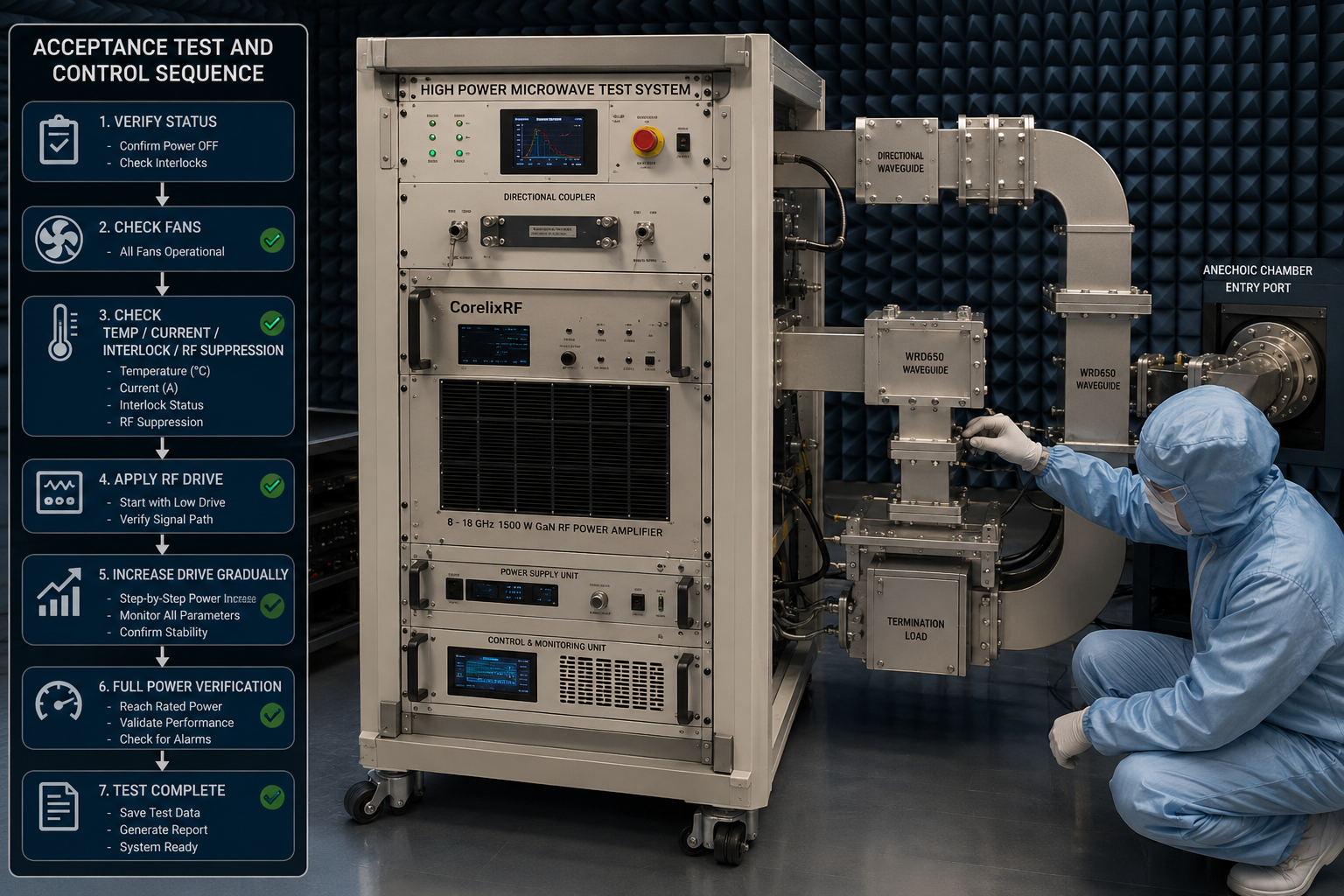
High-power microwave test systems need more than headline wattage. They need controlled gain, RF-safe interfaces, thermal management, monitoring, and a clear acceptance process. CorelixRF CRF-PA-8000M18000M-1500W is specified as an 8-18 GHz 1500 W GaN RF power amplifier for high-power RF systems. The data sheet lists 8,000 to 18,000 MHz operation, 1500 W rated output power, 62 dB minimum small-signal gain, RS485 / LAN control, AC 380 V ±10% power input, air cooling, N-Female RF input, and WRD650 waveguide RF output.
Why 8-18 GHz High-Power Amplifiers Require System-Level Planning
An 8-18 GHz amplifier spans X-band and Ku-band regions where cables, waveguide transitions, couplers, loads, chambers, and antennas can impose serious practical constraints. At 1500 W, a mismatch or procedural error is not a small lab inconvenience. The amplifier should be specified as part of a complete RF path, including measurement couplers, protection thresholds, cooling airflow, emergency stop behavior, and software control sequence.
The CRF-PA-8000M18000M-1500W data sheet describes a GaN SSPA platform for test and measurement instrumentation, communication systems, RF interference / EW system-level testing, and aerospace control. This is not a generic benchtop amplifier. It is a project-specific high-power microwave source where mechanical configuration is listed as TBD and should be finalized during project review.
Critical Specifications to Review
The amplifier lists 1500 W output power and 62 dB minimum small-signal gain. Gain flatness is specified from -6 dB to +6 dB, and gain control range is listed up to 20 dB. Input impedance / VSWR is shown as 50 ohm with 1.5:1 typical VSWR. Maximum input power is listed as 0 dBm. Harmonics are listed from -15 to -8 dBc, noise floor at -20 dBm/MHz, and spurious at -60 dBc.
The RF input is N-Female, while the output is WRD650 waveguide. That output interface changes how the downstream system is designed. Engineers should define waveguide runs, transitions, loads, switches, arcs, flanges, and monitoring points before freezing the mechanical design. Any high power microwave amplifier at this level should be reviewed alongside the final RF layout.
The power input is AC 380 V ±10%, 50/60 Hz. Cooling is air cooling. Operating temperature is 0 to +50 C. Control is RS485 / LAN, with optional LAN remote monitoring, optional forward/reverse power monitoring, GPIB programmable control, and project-specific protocol support where applicable.
Acceptance Testing and Control Sequence
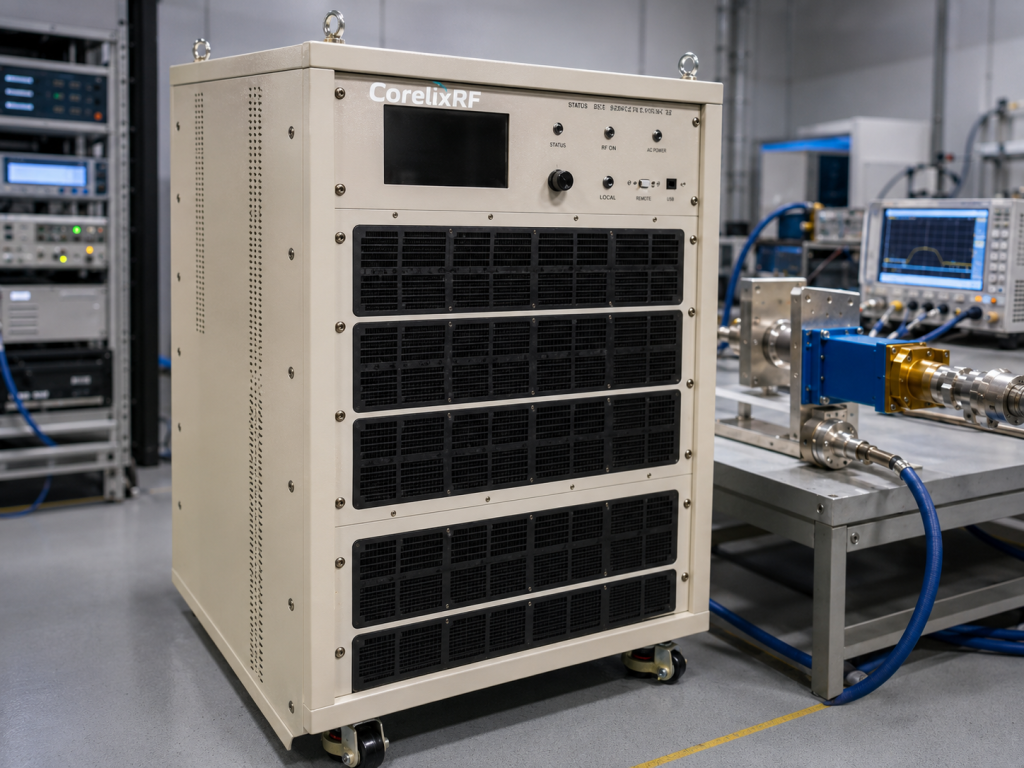
Acceptance testing should define output power by frequency, gain flatness method, harmonic measurement setup, spurious measurement bandwidth, thermal dwell time, and mismatch handling. The source data says final mechanical drawing, test data, and control protocol can be supplied for project review where applicable, so these documents should be requested before system integration begins.
A typical automated sequence should check amplifier status, airflow status, temperature, current, interlock state, and RF inhibit before applying drive. Then the source should ramp gradually while forward power and reflected power are measured. If the test uses pulsed, modulated, or swept signals, the RFQ should clearly define waveform type, duty cycle, peak and average requirements, and dwell time. The data sheet identifies the model as an SSPA platform, but the exact project waveform requirements still need review.
For RF power amplifier procurement, acceptance clauses should also describe what happens after a fault. Does the amplifier latch off, auto-recover, require a command reset, or require physical inspection? Those details matter when the amplifier is integrated into a protected test cell.
When to Use This Instead of a Lower-Power 6-18 GHz Amplifier
A lower-power 6-18 GHz amplifier is useful for driver stages, receiver stress testing, small chamber work, and general microwave validation. The 1500 W 8-18 GHz model is appropriate when the system budget requires substantially more RF output in the X/Ku microwave region and the infrastructure can support AC 380 V power, air cooling, waveguide output, and remote control.
If the final project requires a different enclosure, output interface, monitoring model, or control protocol, CorelixRF can review a custom RF amplifier configuration. Provide frequency range, required power at the load, duty cycle, waveform, allowable harmonics and spurious, rack and airflow limits, control interface, and environmental requirements.
Procurement Checklist for a 1500 W Microwave Amplifier
Before ordering, separate mandatory performance requirements from integration preferences. Mandatory items usually include frequency range, rated output power, gain, allowable gain flatness, harmonic and spurious limits, operating temperature, RF input and output interface, supply voltage, cooling method, control interface, and protection behavior. Preferences may include rack style, display options, logging format, removable panels, or a specific communication protocol. Keeping these categories separate helps the engineering and purchasing teams avoid delays during quotation.
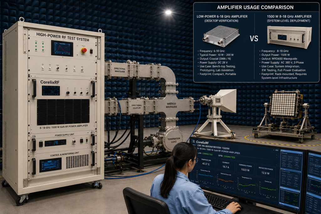
The CRF-PA-8000M18000M-1500W source data lists project-specific mechanical configuration, which means the final drawing should be reviewed before rack planning is frozen. For chamber or range systems, also define waveguide routing, interlock wiring, remote inhibit, emergency stop integration, and the location of forward and reflected power sensors. These details are part of system reliability, not optional accessories.
FAQ
What frequency range does CRF-PA-8000M18000M-1500W cover?
The listed frequency range is 8,000 MHz to 18,000 MHz.
What output power is specified?
The data sheet lists 1500 W rated output power.
What RF output connector is used?
The RF output is listed as WRD650 waveguide, while the RF input is N-Female.
Which control interfaces are listed?
The source data lists RS485 / LAN control, with optional LAN remote monitoring and optional GPIB programmable control where applicable.
What should be clarified before purchase?
Clarify mechanical configuration, cooling, control protocol, waveform, duty cycle, output measurement method, mismatch handling, and acceptance test limits.