
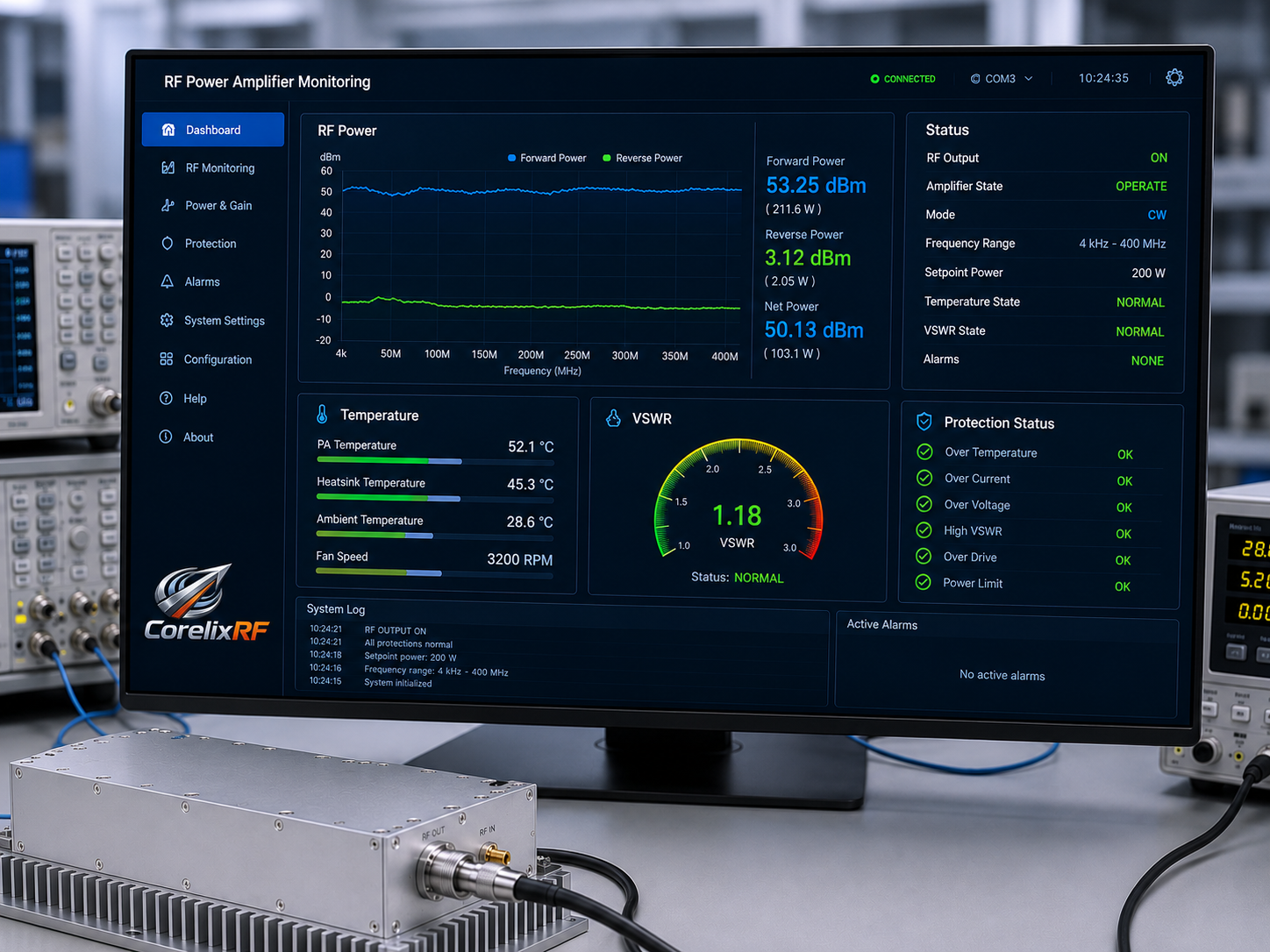
Low-frequency EMC and communication test benches often need power across bands that are awkward for microwave-focused amplifiers. A 4 kHz-400 MHz 200 W EMC RF amplifier gives engineers a solid-state source for low-frequency conducted or system-level testing where broadband coverage, high gain, and protection functions are required. CorelixRF CRF-PA-4K400M-200W-M is specified as an LDMOS SSPA covering 4 kHz to 400 MHz with 200 W saturated output power, 53 dB minimum small-signal gain, SMA-F input, N-F output, and an external heatsink requirement.
Why Low-Frequency EMC Amplifiers Need Careful Specification
At low frequencies, the amplifier is only one part of the energy delivery problem. Fixtures, coupling networks, injection probes, cables, loads, and grounding can dominate the result. A 200 W amplifier can still underperform if the test path is poorly matched or if the fixture losses were not included in the budget. For this reason, an RFQ for a low-frequency EMC RF amplifier should include the test method, load behavior, desired voltage or current at the injection point, maximum dwell time, and cooling constraints.
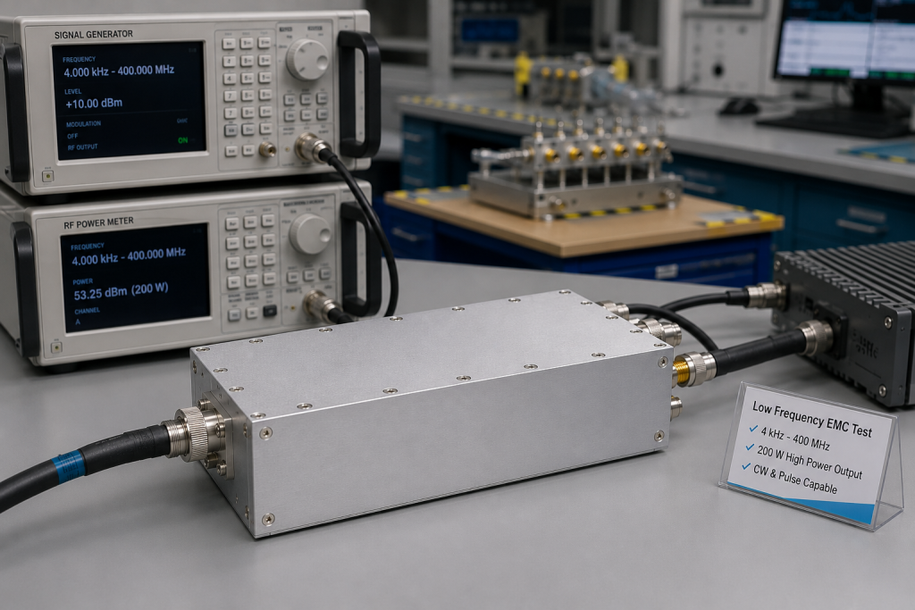
The CRF-PA-4K400M-200W-M data sheet lists 4 kHz to 400 MHz frequency coverage and 200 W saturated output power. Its 53 dB minimum gain means small drive signals can create high output levels, so upstream source limits and software interlocks should be planned carefully. The listed maximum input power is 0 dBm.
Core Specifications from the Data Sheet
The amplifier is designed for a 50 ohm system with a listed input impedance / VSWR of 50 ohm and 2:1 maximum VSWR. Gain flatness is specified from -4 dB to +4 dB. Harmonics are listed at -15 dBc and spurious at -50 dBc. The power supply is split into DC1: 48 V and DC2: 12 V, with typical rated power consumption of 650 W.
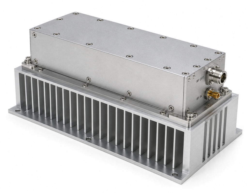
Mechanically, the listed module size is 329.5 x 104.8 x 61 mm and typical weight is 3.5 kg. Cooling is not internal forced air in the same way as a rack unit; the data sheet states that an external heatsink is required. That detail should be treated as a design requirement, not an accessory note. Thermal interface material, mounting pressure, airflow, ambient temperature, and enclosure exhaust all affect usable output.
Monitoring and protection features include real-time temperature monitoring, real-time current monitoring, alarm and fault protection, over-temperature protection, over-drive protection, over-voltage protection, and VSWR protection and alarm functions. Optional forward/reverse power monitoring and a control interface may be available where applicable.
How to Plan a Reliable Low-Frequency Test Chain
Start with the required field, voltage, or current at the device under test. Then work backward through coupling factor, cable loss, mismatch, fixture insertion loss, and safety margin. This tells you whether a 200W solid-state RF amplifier is sufficient or whether the application needs a higher-power platform.
The second step is source control. Because the amplifier has high gain, a signal generator or arbitrary waveform source should be limited in hardware and software. Do not rely only on operator discipline. Use fixed attenuators, source power limits, and a startup routine that verifies RF output disable state before ramping power.
The third step is reflected-power management. Low-frequency fixtures may look very different across a wide sweep. If the project uses changing loads, adapters, probes, or custom injection networks, forward/reverse monitoring can help detect mismatch before a fault becomes a hardware incident. CorelixRF lists optional forward/reverse power monitoring, so it should be raised during project review when test repeatability is important.
Where This Platform Fits in the CorelixRF Lineup
This amplifier is a natural fit for low-frequency conducted immunity development, communication system stimulation, RF interference system-level testing, and broad validation benches that operate below UHF. For higher-frequency radiated immunity, CorelixRF’s 0.6-6 GHz and broadband RF power amplifier families may be more appropriate. For compact or remote-controlled rack systems, engineers should ask whether a custom mechanical and control configuration is available through custom RF amplifier development.
The safest request package should include frequency range, saturated or linear output requirement, waveform, CW or pulsed operation, duty cycle, expected mismatch, control interface, heatsink and airflow plan, and environmental requirements.
Documentation and Safety Details to Include
For low-frequency EMC work, documentation should be as specific as the hardware. Record the amplifier model, heat sink design, airflow direction, fixture type, coupling method, cable type, load rating, source limit, and shutdown threshold in the test procedure. The data sheet states ISO 9001 manufacturing support and CE / RoHS documentation support where applicable, but the final documentation package should be tied to the actual configuration and destination market. This prevents a common procurement problem: assuming that a standard module automatically covers every regulatory or facility requirement.
During installation, leave room for service access and temperature inspection. The compact 329.5 x 104.8 x 61 mm module format can be attractive inside a larger instrument, but the external heat sink requirement means the mechanical design must treat thermal transfer as a primary interface. If the amplifier will run long dwell tests, ask CorelixRF to review expected ambient temperature, mounting method, duty cycle, and alarm thresholds before hardware release.
FAQ
What is the frequency range of CRF-PA-4K400M-200W-M?
The data sheet lists 4 kHz to 400 MHz operation.
What output power is specified?
The amplifier is specified for at least 200 W saturated output power.
Does this amplifier require external cooling hardware?
Yes. The source data states that an external heatsink is required.
Which RF connectors are used?
The input connector is SMA-F and the output connector is N-F.
What protections are listed?
The data sheet lists temperature and current monitoring, alarm/fault protection, over-temperature, over-drive, over-voltage, and VSWR protection and alarm functions.