
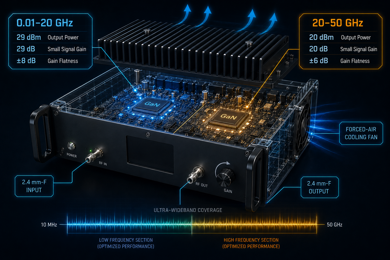
A 10 MHz-50 GHz ultra-wideband RF amplifier is a specialized tool for laboratories that need continuous low-power amplification across an unusually large frequency span. CorelixRF CRF-PA-10M50G-1W is specified as a GaN solid-state RF power amplifier covering 10 MHz to 50 GHz with a 1 W-class output rating. The data sheet lists 29 dBm output power from 0.01-20 GHz and 20 dBm from 20-50 GHz, with corresponding minimum small-signal gain of 29 dB and 20 dB. For engineers building EMC-oriented benches, communication system evaluation paths, RF interference system-level tests, or aerospace control experiments, the main value is coverage, remote control, and repeatable integration.
What Makes a 10 MHz-50 GHz Ultra-Wideband RF Amplifier Different?
Most RF power amplifiers are selected for a defined band where output power, gain, efficiency, and cooling can be optimized. A 10 MHz-50 GHz ultra-wideband RF amplifier is different. It is built for breadth. The system engineer uses it when the test program crosses many bands, when the same control architecture must remain in place, or when a measurement chain needs moderate gain before later frequency-specific stages.
The CRF-PA-10M50G-1W data sheet describes a forced-air mini chassis with 2.4 mm-F RF input and output connectors, AC 220 V ±10% 50/60 Hz supply, RS485 / LAN control, real-time temperature monitoring, real-time current monitoring, and alarm protection. Optional functions can include input power detection, forward/reverse power monitoring, GPIB programmable control, LAN remote control, and project-specific protocol support.
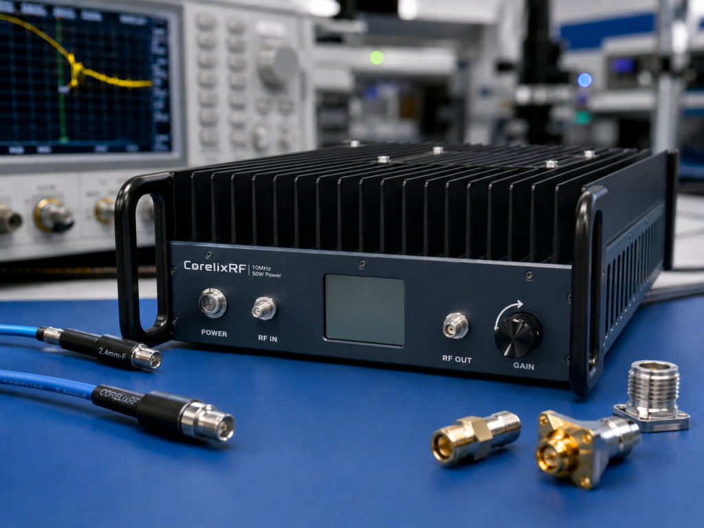
That combination makes the amplifier relevant to RF testing and validation teams that need a controlled broadband gain block rather than a high-power single-band source.
Key Specifications for Measurement and EMC-Oriented Use
The output power split is the first specification to understand. The data sheet lists 29 dBm typical output power from 10 MHz to 20 GHz and 20 dBm typical output power from 20 GHz to 50 GHz. It is therefore not a constant-wattage amplifier across the entire span. Test plans should set frequency-dependent limits and avoid assuming the same available margin above 20 GHz.
Small-signal gain is also split by band: 29 dB minimum from 10 MHz to 20 GHz and 20 dB minimum from 20 GHz to 50 GHz. Gain flatness is listed as ±8 dB from 10 MHz to 20 GHz and ±6 dB from 20 GHz to 50 GHz. In practice, that means the software layer should store calibration factors for each frequency point or band segment.
The RF connector choice matters. 2.4 mm connectors support the upper frequency range, but every adapter, cable, torque wrench process, and mating cycle affects repeatability. For wideband measurement chains, define a controlled connector plan before acceptance testing.
Integration Notes for Automated RF Systems
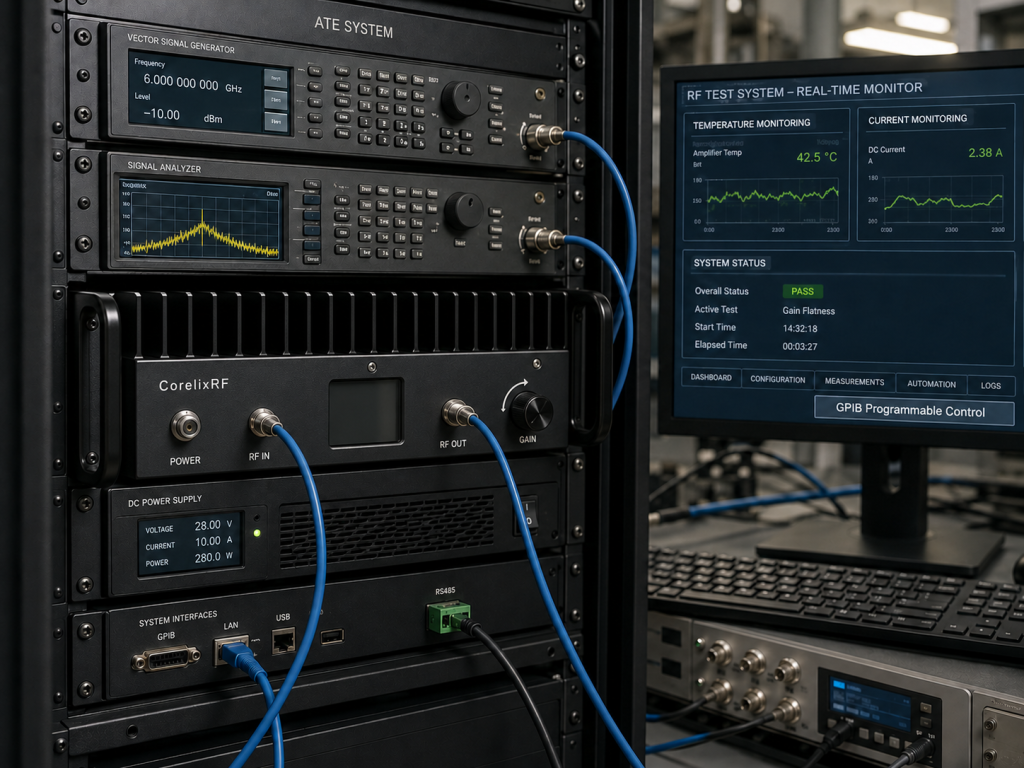
Because the amplifier supports RS485 / LAN control, it can be incorporated into automated test sequences. Engineers should request the final control protocol, status registers, alarm behavior, and recovery procedure during project review. When a test system spans 10 MHz to 50 GHz, a clear command and logging model is more important than a generic front-panel workflow.
A recommended sequence is to initialize the amplifier, confirm temperature and current status, set the required gain or operating state, enable the RF path, ramp the source level, measure output through a calibrated coupler or sensor, and then log the final source setting, measured output, frequency, temperature, and current. This creates a clean record for troubleshooting.
For broadband RF power amplifier chains used near sensitive receivers, include a switched attenuator or limiter where appropriate. The data sheet lists a maximum input power of 5 dBm. Keeping upstream source drive under control protects the amplifier and improves repeatability.
When It Fits Better Than a Narrowband High-Power Amplifier
This 1 W-class ultra-wideband platform is strongest when the project needs coverage, continuity, and instrumentation control. It is not intended to replace a high-power EMC immunity amplifier or a dedicated high-power chamber source. For radiated immunity or conducted immunity programs that require higher field strength, CorelixRF’s EMC RF amplifier families may be a closer match. For high-power microwave or mmWave test applications, a banded high-frequency amplifier may provide more output margin.
A useful RFQ should identify the test standard or internal procedure, target frequency range, required output at the fixture or antenna, waveform type, maximum duty cycle, preferred control interface, available rack space, and any acceptance data format. That information helps CorelixRF determine whether the CRF-PA-10M50G-1W is enough by itself or should act as a driver stage inside a broader chain.
For procurement teams, the most useful comparison is not only the frequency headline. Ask how the amplifier will be calibrated, which control interface will be used in the final rack, what alarm data can be logged, and whether optional monitoring should be included before acceptance testing begins. Those details help the same hardware move from engineering evaluation into repeatable production or qualification workflows.
FAQ
What frequency range does CRF-PA-10M50G-1W cover?
The specified frequency range is 10 MHz to 50 GHz.
Is output power the same across the full frequency range?
No. The data sheet lists 29 dBm typical output power from 10 MHz to 20 GHz and 20 dBm typical output power from 20 GHz to 50 GHz.
Which control interfaces are listed?
The data sheet lists RS485 and LAN control, with optional GPIB programmable control and project-specific protocol support where applicable.
Can it be used for EMC testing?
It can support EMC-oriented measurement and system-level testing where the 1 W-class output and frequency-dependent limits match the requirement. Higher-power EMC applications may require another amplifier family.
What supply and cooling are specified?
The source data lists AC 220 V ±10%, 50/60 Hz input power and forced-air cooling in a mini chassis.