
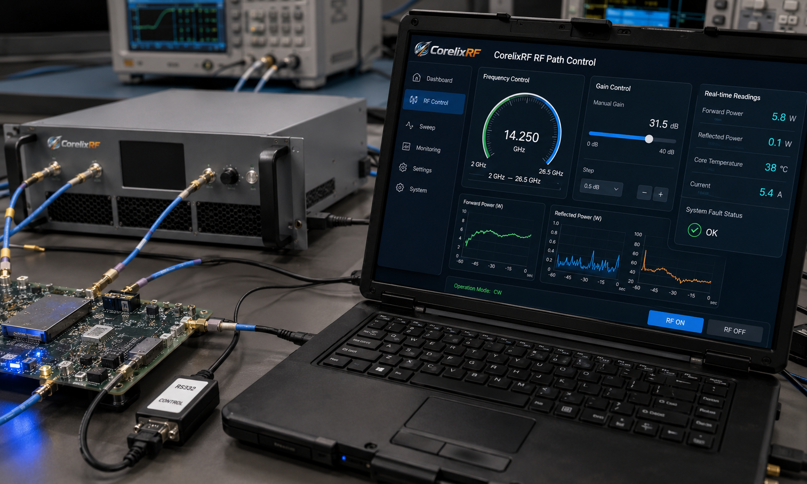
When an RF test bench must cover S-band, C-band, X-band, Ku-band, and K-band without changing amplifier hardware, a 2-26.5 GHz wideband RF power amplifier becomes a practical building block. CorelixRF CRF-PA-2000M26500M-6W is a GaN solid-state amplifier specified for 2 GHz to 26.5 GHz operation with 6 W rated RF output power, 36 dB minimum small-signal gain, 2.92 mm female RF input and output connectors, forced-air cooling, and RS232 control. It is best understood as a compact integration amplifier for test and measurement instrumentation, communication system evaluation, RF interference system-level testing, and aerospace control projects where coverage and control matter more than single-band peak power.
Why a 2-26.5 GHz Wideband RF Power Amplifier Fits Multi-Band Labs
A 2-26.5 GHz wideband RF power amplifier helps engineers keep one calibrated chain across many microwave bands. Instead of switching between narrowband modules, the lab can use one amplifier for frequency-swept validation, receiver desense checks, SDR path evaluation, and early subsystem integration. That does not remove the need for proper power sensors, attenuators, couplers, and interlocks, but it reduces the number of amplifier swaps during repeatable testing.
The CRF-PA-2000M26500M-6W data sheet lists 6 W rated output power across the supported frequency range and 36 dB minimum small-signal gain. Gain flatness is specified as -8 dB to +8 dB, which is important to plan for in automated test scripts. A wideband chain should not assume identical available output at every frequency point. Engineers should profile the full path with cables, adapters, couplers, switch matrices, and antennas or loads installed.
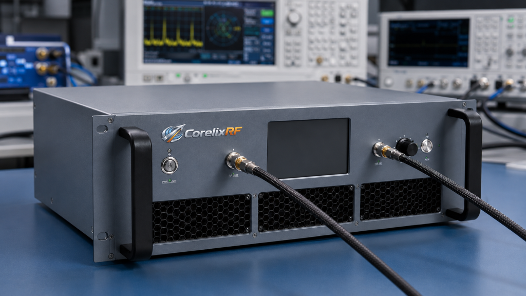
For users building SDR RF amplifier integration benches, the 2-26.5 GHz span can support broad waveform work, front-end validation, and frequency-agile signal path checks. The amplifier can sit after a signal generator or SDR exciter when the source power is controlled carefully and the required output level is within the 6 W class.
Key Specifications to Confirm Before RFQ
The amplifier is specified for a 50 ohm system with 2.92 mm-F input and output connectors. The listed input impedance / VSWR requirement is 50 ohm with 2:1 maximum VSWR. Harmonics are listed at -15 dBc and spurious at -60 dBc. The power supply requirement is 18 V / 6 A DC, and the mechanical form factor is 240 x 160 x 50 mm. Operating temperature is 0 to +40 C with forced-air cooling.
Those details create several RFQ checkpoints. First, confirm whether the project needs the 6 W rating at every operating point or only within selected sub-bands. Second, define the maximum input power, expected waveform type, CW or modulated duty cycle, and whether gain control must be manual, software-controlled, or closed-loop. Third, define the cooling path. A compact module still needs enough airflow and exhaust clearance to keep temperature monitoring from becoming the limiting factor.
The data sheet also lists up to 15 dB gain control range. That is useful when a test platform must step output level across many frequencies, but the control method should be confirmed with CorelixRF during project review. The source data lists RS232 control, temperature monitoring, current monitoring, alarm protection, over-temperature protection, over-drive protection, over-voltage protection, and VSWR protection and alarm functions. Optional forward/reverse power monitoring and input power detection may be available where applicable.
How to Use It in a Broadband Test Bench
A good broadband RF amplifier installation begins with the full chain budget, not only the amplifier rating. Start with the signal source maximum output, add required attenuation for source protection, include cable and switch loss, and then calculate expected amplifier input power. Keep the input below the specified limit and avoid driving the amplifier into uncontrolled compression unless the test explicitly requires it.
Next, plan measurement points. A directional coupler after the amplifier gives forward power visibility, while reflected power monitoring helps identify mismatch conditions before they become fault events. For automated systems, log amplifier current, temperature, commanded gain state, output frequency, and measured forward power together. This makes it easier to distinguish amplifier behavior from fixture loss, adapter wear, load mismatch, or test script errors.
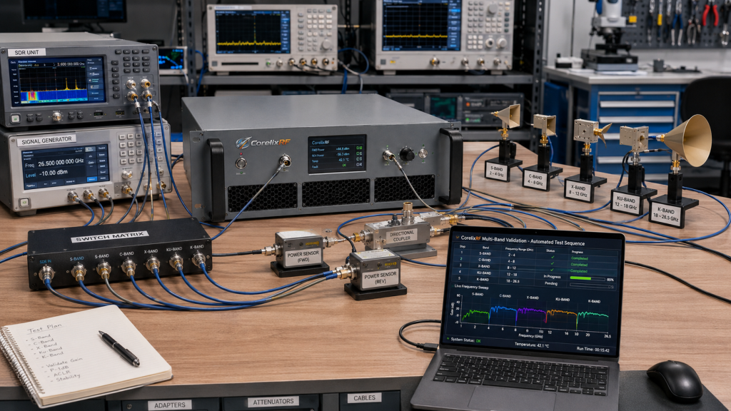
Finally, document connector discipline. At 26.5 GHz, 2.92 mm connectors require clean mating surfaces, correct torque, and phase-stable cables if repeatability matters. A wideband amplifier can only perform as well as the RF interface around it.
When to Choose a Higher-Power or Custom RF Amplifier Instead
A 6 W 2-26.5 GHz amplifier is a strong fit for broadband driver chains, receiver testing, SDR validation, compact microwave benches, and controlled system-level testing. It may not be the right selection when the test requires tens or hundreds of watts over narrower ranges, radiated immunity power levels, or large chamber path losses. In those cases, a higher-power RF power amplifier or a custom RF amplifier can be reviewed around the exact frequency band, waveform, duty cycle, output connector, cooling method, and enclosure requirement.
CorelixRF can also review project-ready control functions, including optional forward/reverse power monitoring, input power detection, and interface requirements. The safest RFQ package includes the target frequency range, output power at the load, waveform type, CW or pulse operation, duty cycle, control interface, mechanical constraints, and environmental requirements.
FAQ
What is the rated output power of CRF-PA-2000M26500M-6W?
The data sheet lists 6 W rated RF output power across a 2 GHz to 26.5 GHz operating range.
Which RF connectors does this 2-26.5 GHz amplifier use?
The specified RF input and RF output connectors are 2.92 mm female connectors.
Is the amplifier suitable for SDR test platforms?
Yes, it can support SDR and broadband RF test integration when the required output power, source drive level, duty cycle, cooling, and control interface match the project requirements.
What protection features are listed?
The source data lists temperature and current monitoring, alarm/fault protection, over-temperature, over-drive, over-voltage, and VSWR protection and alarm functions.
What should be provided for a technical review?
Provide frequency range, required output power, waveform type, CW or pulse operation, duty cycle, control interface, mechanical constraints, and environmental requirements.