
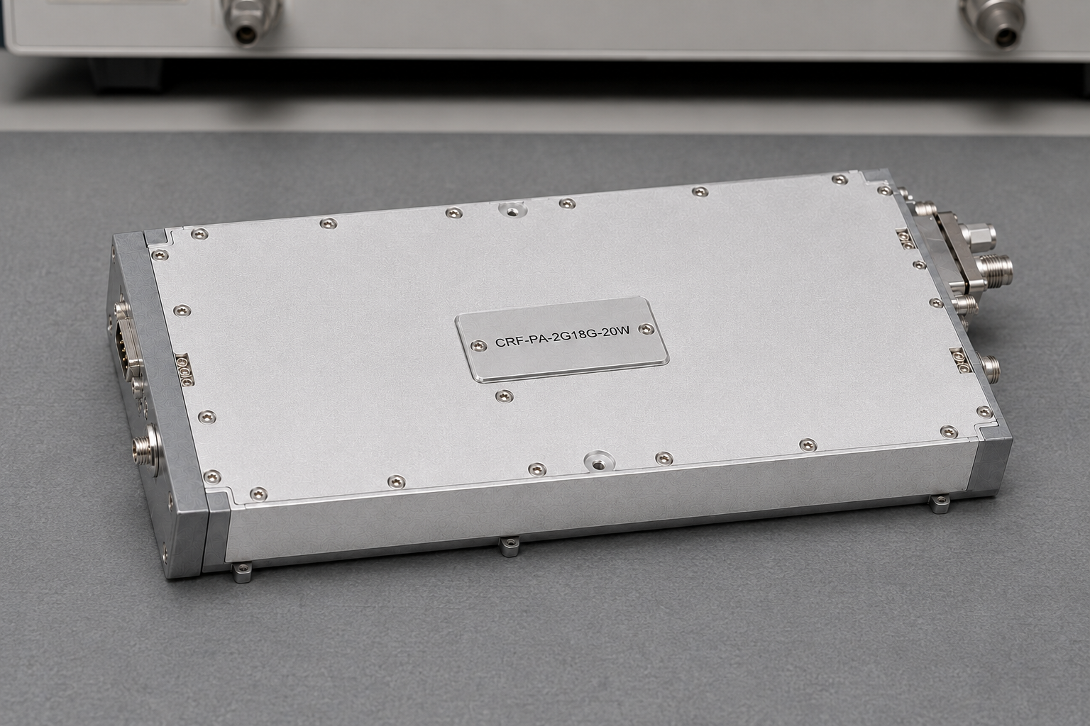
The amplifier says 20 W on the label. The reading at the DUT says otherwise.
That usually starts an uncomfortable conversation. Is the amplifier low? Is the power meter wrong? Should the source level be increased? Before touching the source, it is worth checking what the two numbers actually describe.
We see this most often when a wideband RF power amplifier is added to an existing test bench. The RF path may have grown over time: one cable, two adapters, a directional coupler, perhaps an attenuator in front of the sensor. None of those parts looks like a major problem by itself. Together, they can take a noticeable bite out of the available power—especially when the setup has to work from 2 to 18 GHz.
The example here is the CorelixRF CRF-PA-2000M18000M-20W, a 2–18 GHz GaN solid state power amplifier (SSPA) module rated at 20 W. The same checks apply to many broadband RF power amplifier installations.
Which 20 W are we talking about?
Start by marking the point where the power is required.
Source → input cable → amplifier → output cable → coupler → DUT
                               ↑                          ↑
                    amplifier output                 DUT input
Twenty watts at the amplifier connector and 20 W at the DUT are not the same requirement. If the target is at the DUT, the output cable, coupler, adapters and any other components between those two points belong in the power budget.
This sounds obvious, but reference-plane mix-ups are common. A factory test may end at the amplifier output connector while the system test is taken several components farther downstream. Both readings may be correct.
Loss also changes across a wide band. A cable assembly that looks unremarkable at the low end may have a greater effect closer to 18 GHz. The useful question is not simply, “How much loss is in the cable?” It is, “How much loss is in the complete path at the frequencies we care about?”
Resist the urge to turn up the generator
The module is specified with at least 43 dB small-signal gain. Its maximum input power is 0 dBm.
Small-signal gain is helpful when estimating a starting drive level. It does not mean that the amplifier will keep adding 43 dB as it approaches rated output. RF amplifier gain measured in the small-signal region cannot be carried straight into large-signal operation; once the amplifier leaves that region, the simple relationship no longer holds.
There is another important detail: 0 dBm is a limit, not a target drive setting.
When the output reading is low, raising the generator level can hide the real problem and eventually overdrive the amplifier. A better method is to start low, measure the power that actually reaches the RF input, then increase it in controlled steps. Watch the amplifier current and alarm state at the same time.
Do not rely only on the number shown on the generator. The input cable and any source-side components sit between that display and the amplifier input.
With a modulated waveform, the setup needs more information than an average input level. Bandwidth, peak-to-average ratio and the required linearity all affect the operating point. The module datasheet does not give a one-size-fits-all EVM, ACPR or backoff value, so the 20 W rating should not be used to invent one.
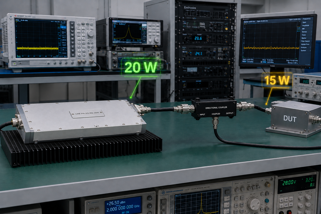
Walk the output path
When the amplifier output has not yet been measured directly, break the path into sections.
Measure at the amplifier output first, using a suitable test arrangement. Then move to the far end of the output cable, after the coupler, and finally to the DUT input. Repeating those measurements at a few relevant frequencies usually tells a clearer story than repeatedly adjusting the source.
If the first point is correct and the last is low, the missing power is downstream of the amplifier. If one section suddenly becomes worse near the upper end of the band, check the bandwidth of the component, its connection and the calibration used for that measurement.
The CRF-PA-2000M18000M-20W has SMA female RF input and output connectors and is designed for a 50-ohm system. That does not automatically qualify every SMA cable or adapter already lying on the bench. In a high frequency RF amplifier setup, frequency range, power handling and physical condition still matter.
A worn adapter can be especially frustrating. It may work well enough to pass a quick continuity check while giving inconsistent RF results after it has been disconnected and reconnected a few times.
Try a known load
The module’s documented input/output VSWR limit is 2:1. It also includes VSWR-related alarm and protection functions.
If the output changes sharply at certain frequencies, substitute a known, well-matched load and repeat the test. This is a quick way to separate a broadband RF amplifier or path problem from a DUT mismatch.
Filters and antenna-related assemblies deserve particular attention because their impedance can change considerably across frequency. A DUT that behaves well at one point in the band may reflect much more power at another. Depending on the condition, the amplifier may report an alarm or change state to protect itself.
Forward and reverse power monitoring are available as an option on this module. For systems that regularly see changing loads, that information can be useful. Before ordering it, decide what the controller needs from the feature. Accuracy, update rate, data format and the action following an alarm are more useful specifications than simply requesting “power monitoring.”
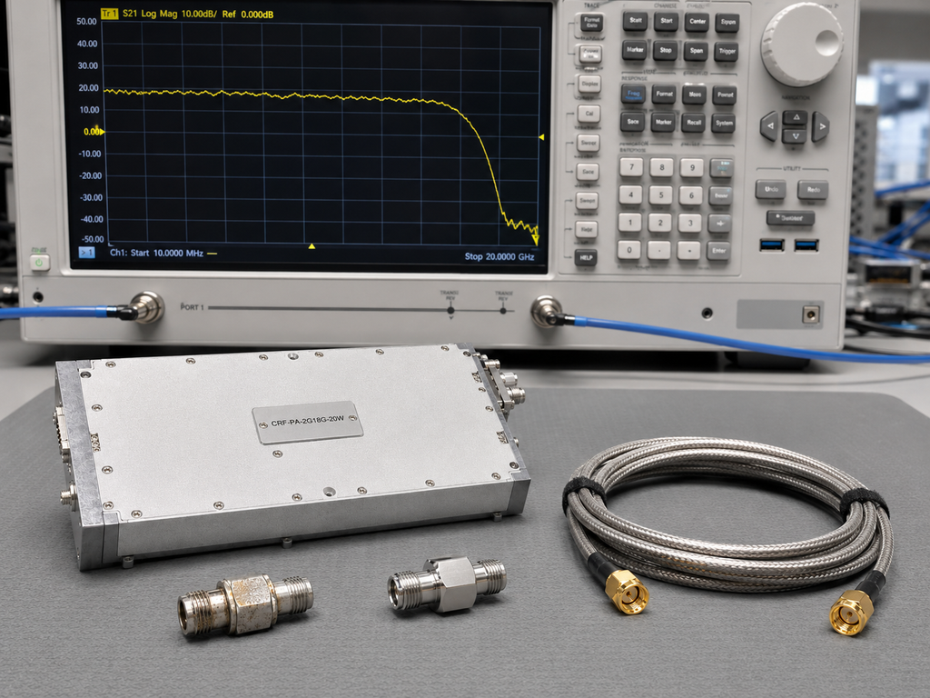
Does the output fade after a few minutes?
If the bench produces the expected result after startup but drifts as the test continues, look at temperature before changing RF settings.
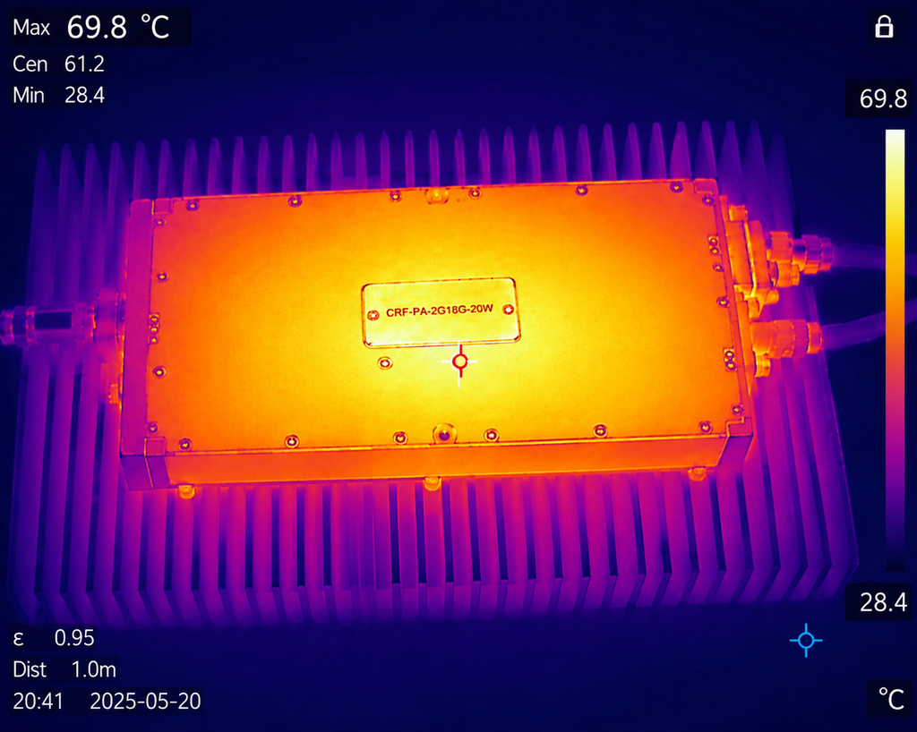
The module is 200 × 100 × 23 mm, weighs about 1 kg and requires an external heatsink. Its specified operating-temperature range is 0°C to +50°C. Temperature monitoring and over-temperature protection are included, but neither can make up for poor thermal contact or blocked airflow.
Check the module mounting surface and thermal interface material. Make sure the base is seated evenly on the heatsink. Look at what happens after the enclosure is closed: cables can block airflow, and the air entering the amplifier area may already have been warmed by another assembly.
Log module temperature alongside RF output. A fault that follows time and temperature is much easier to recognize when the two traces are viewed together.
Continuous operation and short test bursts can produce very different thermal results. If the application needs long CW runs, a successful brief bench test is not enough evidence that the cooling arrangement is finished.
Measure 28 V at the module
The green light on a DC supply only confirms that the supply is on.
This amplifier module requires 28 V DC. The available datasheet does not state current consumption, so the supply and cabling should be sized from the confirmed project requirement—not estimated from the 20 W RF rating.
During a high-output test, measure voltage at the module power input. Long leads, undersized conductors and connector resistance can produce a drop that is not visible on the supply’s front panel.
The module provides current monitoring as well as over-voltage protection. Recording input voltage, current, temperature and RF output during the same run makes diagnosis much easier. A change that follows voltage points in a different direction from one that follows heatsink temperature.
Startup order is worth checking too. The 28 V supply, amplifier enable and generator RF output should be coordinated so that the source does not apply a high drive level before the amplifier is ready.
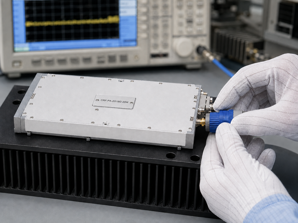
What a useful test record looks like
A screenshot of a favorable power reading is not much help six months later.
A useful record identifies the amplifier configuration, input signal, drive level, supply condition and measurement reference plane. It also shows what was installed between the amplifier and the sensor, and whether any alarm occurred during the run.
Record the frequencies the application actually uses. If the system only operates from 2 to 6 GHz, test data for that range may be the relevant evidence. If continuous 2–18 GHz coverage is required, a handful of convenient points cannot stand in for the full requirement.
Keep the test tied to the application. More data is not automatically better data if the conditions are unclear.
A bench sequence that usually saves time
For a low reading at the DUT, we would normally check the microwave power amplifier setup in this order:
- Mark the required power reference plane.
- Measure the real drive level at the amplifier input.
- Increase drive carefully without exceeding the 0 dBm input limit.
- Measure loss through the output path in sections.
- Replace the DUT with a known matched load.
- Review current, temperature and alarm status.
- Inspect the heatsink installation and airflow.
- Measure the 28 V supply at the module under load.
- Repeat the checks at the frequencies that matter to the project.
This sequence is not complicated, but it prevents several variables from being changed at once. By the end, the problem is usually narrowed to the drive path, output path, load, cooling arrangement, supply—or the amplifier itself.
Send the RF chain with the inquiry
When asking an RF power amplifier manufacturer to review a 2–18 GHz, 20 W requirement, include a simple block diagram if possible. Show the source, amplifier, cables, coupler and load. Add the signal type, operating frequencies, required power reference plane, expected load mismatch, run time and cooling arrangement.
That information is more useful than frequency and wattage alone. It lets the factory review the amplifier in the system where it will actually work.
The label tells you what the module is rated to deliver at its output. The DUT reading tells you what survived the rest of the bench. Finding the difference means looking at the whole path.