
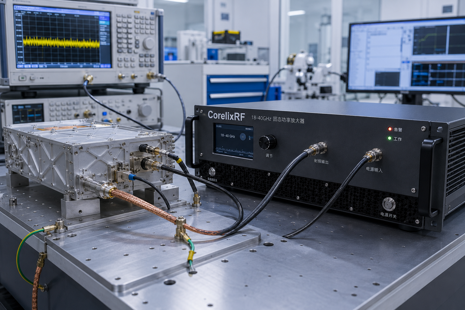
Choosing an RF power amplifier gets harder as the frequency goes up. An 18–40 GHz solid state power amplifier, often shortened to SSPA, sits in a high-frequency RF amplifier category where the number printed beside the model name is only the beginning of the discussion. A 20 W amplifier may be enough for one test bench and completely wrong for another, even when both systems appear to need the same frequency coverage.
The difference usually comes down to details that are easy to miss at the start: what kind of signal is being amplified, where the output power must be measured, how much is lost between the amplifier and the load, and whether the rack and cooling system can support the final hardware.
CorelixRF’s 18–40 GHz RF power amplifier family currently uses 5 W, 20 W, 40 W and 70 W as starting classes for engineering review. These wideband RF power amplifier options are useful for narrowing the field, but they are not a substitute for defining the actual RF chain.
This article looks at that selection process through five common project situations. The goal is not to assign one power class to each application. It is to show what changes from one system to another, and what information an engineering team needs before a responsible recommendation can be made.
Start with the power requirement—not the wattage label
One of the first questions should be: what does the required output power actually mean?
The headline power in current CorelixRF product records is identified using a saturated output power, or Psat, field. Psat, P1dB and linear output describe different operating points. They should not be treated as interchangeable values.
That distinction matters most when the input is modulated. A signal with a high peak-to-average power ratio cannot normally be evaluated by looking at saturated power alone. The useful operating point will depend on the waveform, bandwidth and linearity target. If the project has EVM or ACPR/ACLR requirements, those conditions belong in the RFQ from the beginning.
There is also no single output-backoff value that works for every waveform and every amplifier. Applying a familiar rule of thumb without looking at the actual signal can leave too little linearity margin or lead to unnecessary oversizing.
For a CW test, the question may be relatively direct. For a wideband modulated signal, it is not. A CW amplifier, a pulsed RF amplifier and a linear RF amplifier may all be judged against different operating conditions, even when their frequency ranges overlap. Before comparing 5 W, 20 W, 40 W and 70 W, make sure everyone is discussing the same definition of power.
Where does the power need to be available?
Many projects do not really need a certain power at the amplifier connector. They need it at a DUT, a load, a waveguide interface or an antenna feed after several other components.
A simple RF chain might look like this:
Signal source → RF power amplifier → cable / adapter / coupler / waveguide → DUT or loadEvery item after the amplifier can reduce the power available at the final reference plane. At 18–40 GHz, adapters and transitions that look insignificant on a block diagram may have a meaningful effect on the budget.
If the target is defined at the downstream reference plane, the basic relationship is:
Required amplifier output ≥ required load-side power + RF-path loss + operating marginThe exact loss and margin have to come from the project. They should not be copied from a generic example. Frequency, cable routing, connector condition, couplers, waveguide sections and the test setup can all change the result.
This is why a request such as “18–40 GHz, 20 W” is usually incomplete. It does not say whether 20 W is required at the amplifier, after the RF path or at the device being tested.
How the four starting classes should be used
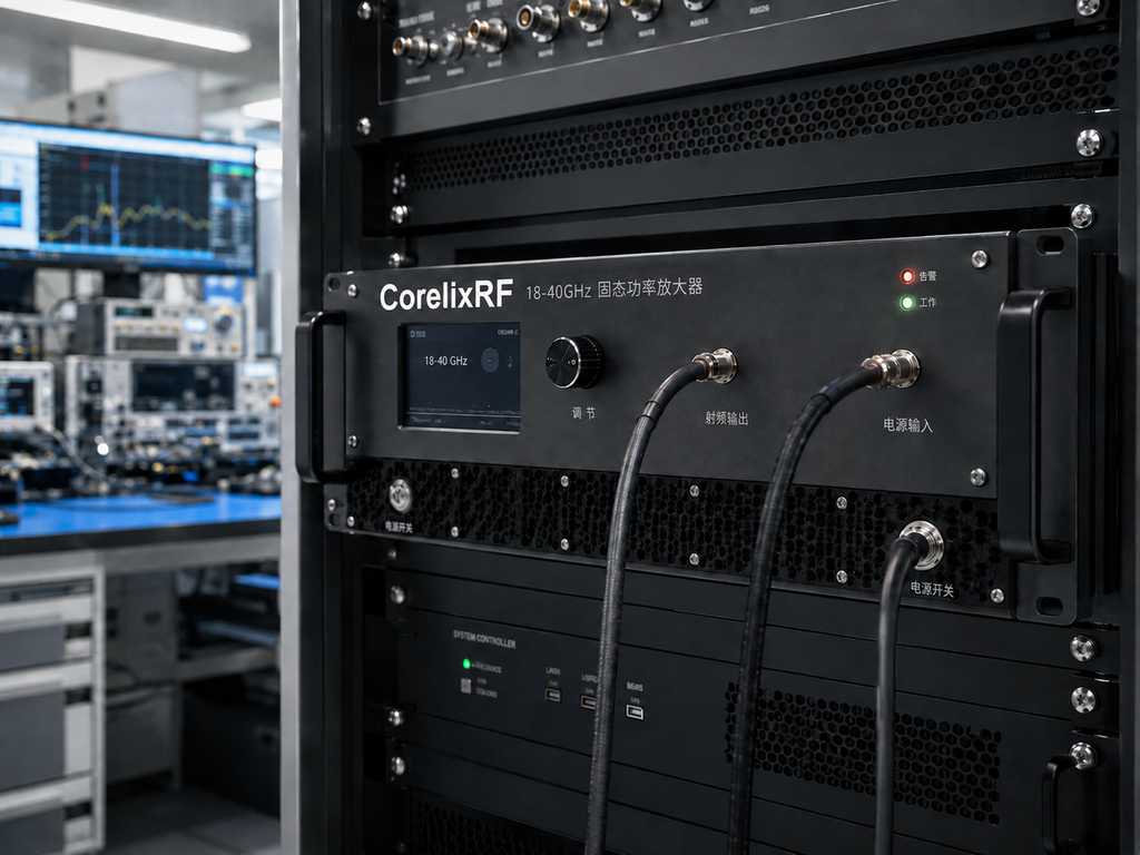
The 5 W, 20 W, 40 W and 70 W classes are best treated as points where a technical conversation begins.
A project near the lower end may start with the 5 W class, then check whether the source can drive it correctly and whether the required RF interface, supply and control arrangement are suitable. A project around 20 W may need closer attention to the waveguide or coaxial output path, rack supply and cooling. Moving toward 40 W or 70 W makes the installation discussion more important: facility power, airflow, available rack space, duty cycle and the planned acceptance method should be considered early rather than after the RF design has been frozen.
Higher power is not automatically safer. It can provide useful margin, but it can also increase the size and complexity of the system. The right starting class is the one that meets the defined output requirement with an appropriate margin while remaining practical for the source, RF path and installation.
Detailed performance still has to be reviewed for the selected model and conditions. A class name by itself does not establish full-band minimum output, linearity, gain behavior, connector arrangement or chassis configuration.
Scenario 1: driving a DUT on a wideband test bench
Consider a laboratory setup used to evaluate components or subsystems across a broad frequency range. The signal generator feeds the amplifier, and the amplifier drives a DUT through cables, adapters and perhaps a directional coupler.
In this case, the most useful question is rarely “Which amplifier has the largest output?” It is “How much calibrated power must reach the DUT at each important test frequency?”
The answer depends on the source level, source-side loss, amplifier drive requirement and the loss between the amplifier and the DUT. The weakest point in the required sweep matters more than the best-looking point on a curve.
The test engineer should define the sweep range, frequency points, signal type, required DUT input, reference plane and allowable variation. If the system is automated, the control interface and recovery behavior also need to fit the test software. A unit that meets the RF target but cannot be integrated into the automation environment may still be the wrong choice.
Measurement evidence should be reviewed with the same discipline. A useful curve needs to match the model, frequency range, power definition, input drive, supply, temperature and reference plane. A plot from another configuration may be interesting, but it does not prove how the requested unit will behave in the planned setup.
Scenario 2: validating a mmWave communication signal
A communication test setup changes the conversation because the amplifier is now handling a waveform rather than a simple CW tone. This is why RF power amplifiers for wireless communications are usually reviewed against waveform and linearity requirements, not saturated output alone.
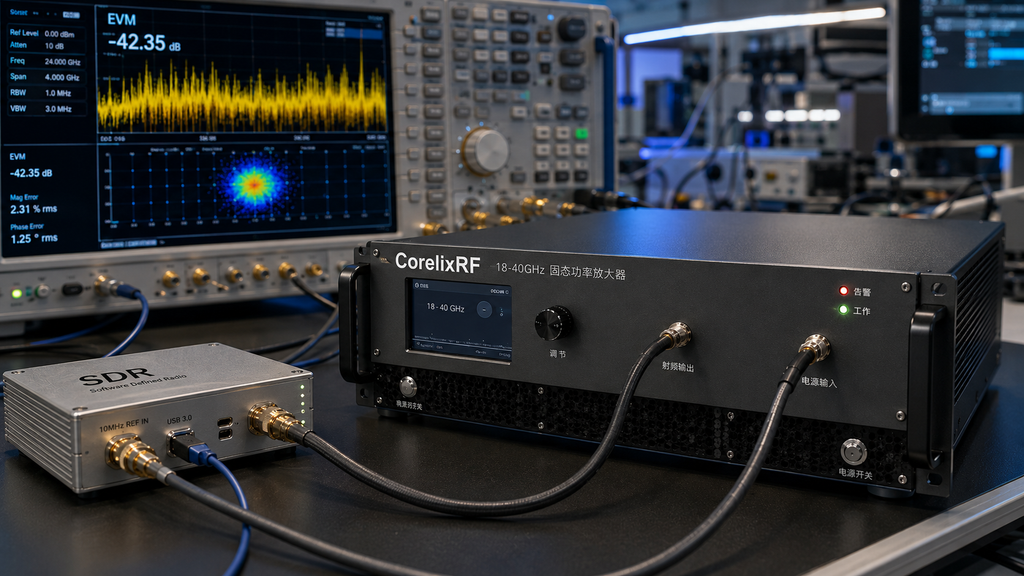
Suppose an SDR or vector signal source generates a wideband modulated signal, which then passes through the amplifier into a receiver, channel emulator, antenna subsystem or test load. The saturated power class may help identify a starting platform, but it does not tell the engineer how much average modulated output will be available at the required linearity.
The project team needs to provide the waveform, instantaneous bandwidth, PAPR, average and peak power targets, and the relevant EVM or ACPR/ACLR limits. The output reference plane must also be clear. A linearity target at the amplifier connector is different from a target measured after a lossy transition or at the far end of a test path.
This is also where a narrower frequency requirement can change the review. If the system only operates in part of the 18–40 GHz range, say so. A focused window may follow a different engineering path. At the same time, data from a narrower 26.5–40 GHz configuration should not be used to claim performance across the complete 18–40 GHz band.
The practical lesson is simple: send the actual signal requirement, not just the carrier frequency and wattage.
Scenario 3: an authorized, controlled RF interference test
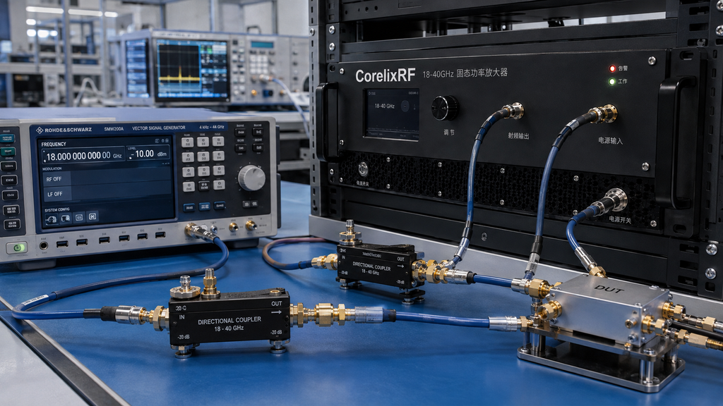
In a controlled RF interference or system-level susceptibility test, the amplifier is one part of a larger test environment. The objective may be to deliver a defined conducted power or field condition at a known point while maintaining control over the RF path and test sequence.
Here, the downstream system matters as much as the amplifier. Couplers, waveguide sections, antenna feeds, loads and shielding arrangements affect what reaches the test point. If the output requirement is defined at the antenna feed or another point after the amplifier, those losses must be included.
The load environment also deserves attention. Expected mismatch, reflected power and operating duty can influence the required monitoring and protection strategy. Forward and reverse power monitoring, alarms, interlocks, shutdown behavior and recovery logic should be specified rather than assumed.
This type of application should always be described as authorized and controlled testing. An amplifier specification does not establish regulatory permission, test-site suitability or operational effectiveness. Those issues belong to the project’s own authorization, safety and compliance process.
For the RFQ, it helps to include the authorized frequency window, waveform, duty cycle, required reference plane, RF-path drawing, load condition, control method and the acceptance records expected from the supplier.
Scenario 4: laboratory validation of an aerospace RF subsystem
An aerospace-related project often begins with a broad application label, but “aerospace” is not a technical specification. A laboratory setup for subsystem validation may have very different requirements from flight hardware, a payload interface or a production test station.
The amplifier review should therefore stay close to the actual laboratory task. Which frequencies are required? Is the signal CW, pulsed or modulated? What interface must mate with the subsystem? What are the supply, grounding, rack and airflow constraints? Which configuration and test records will procurement need?
Traceability is often a central concern. The model and revision in the quotation, drawing, test record and delivered unit should refer to the same agreed configuration. If a factory acceptance test or witnessed measurement is required, the measurement method, reference plane, limits and records should be discussed before the order is placed.
It is equally important not to turn an application direction into a qualification claim. A product being reviewed for aerospace subsystem testing does not mean that it is aerospace-certified or approved for flight. Any certification or compliance requirement must be tied to the exact product, legal entity and project scope.
Scenario 5: connecting an SDR source, amplifier and antenna
An SDR-to-amplifier-to-antenna chain is a good example of why isolated component selection can fail.
The SDR or RF source must provide enough drive over the required band without becoming the first source of distortion. The amplifier must operate at the right point for the waveform. The output path must then carry the signal through the required connector or waveguide transition to the antenna or load.
If each part is chosen independently, several problems can appear. The source may not drive the amplifier to the intended output. A transition may consume more margin than expected. The antenna-side mismatch may not match the assumed load condition. Or the complete chain may meet the power target but miss the linearity requirement.
A useful inquiry includes a block diagram of the chain, source maximum output, source-side loss, waveform and bandwidth, required amplifier output, downstream loss, antenna or load interface, expected VSWR environment and control architecture.
This is also a case where system-level integration content can help. CorelixRF’s 18–40 GHz amplifier integration guide covers the interface, RF-path and installation questions in more detail.
Full-band coverage or a focused operating window?
The application does not determine the frequency requirement. Two communication systems or two test benches can use completely different parts of the spectrum.
If continuous 18–40 GHz coverage is genuinely required, the review should focus on the behavior across the required span, including the weakest relevant point. The evidence for a broadband RF power amplifier should match that full-band requirement rather than a narrower, more favorable test window.
If the system only uses a defined sub-band, a focused-window review may be more appropriate. That does not automatically mean better performance, lower cost or faster delivery. It simply gives engineering a more accurate problem to evaluate.
Keeping these two paths separate also prevents a common evidence mistake: using a strong result from a narrower band as proof of full 18–40 GHz capability.
Do not leave the interface and cooling review until the end
At 18–40 GHz, the RF interface is part of the electrical and mechanical design. A microwave power amplifier in this range may use a coaxial path, a waveguide path or a project-specific transition, each of which affects loss, mating hardware, the calibration plane and the physical layout. The final connector or flange and its orientation should be confirmed in the applicable drawing.
The same is true for the installation. Rack height alone does not establish that an amplifier will work in a particular cabinet. Facility supply, allowable electrical load, duty cycle, airflow direction, inlet temperature, cabinet backpressure, service clearance and nearby heat sources all matter.
These questions become more important as the starting power class increases, but they should not be ignored for lower-power configurations. A technically correct RF selection can still fail at integration if the enclosure, power or cooling assumptions are wrong.
What should the buyer ask to review?
The useful document set depends on the model, configuration and buying stage. It may include an applicable datasheet, output-power or gain data with stated conditions, RF and mechanical drawings, control-protocol information, an agreed FAT or unit-test scope, and configuration or inspection records.
The key word is “applicable.” Not every document exists for every model at every stage, and a general webpage should not be treated as the final acceptance specification.
Before relying on a curve, check the model or unit identity, document revision, frequency points, power definition, drive, supply, temperature, duty condition, reference plane, calibration and test date. CorelixRF’s RF test and delivery documentation guide provides a broader view of how document requirements can be prepared before shipment and incoming inspection.
A practical RFQ for an 18–40 GHz amplifier
The fastest way to improve an amplifier recommendation is to send one complete project definition rather than several short messages with isolated specifications.
Include the required frequency range, whether coverage must be continuous, the signal type, output-power definition, reference plane, waveform and linearity targets, estimated RF-path loss, source capability, RF interfaces, supply and cooling constraints, control requirements, quantity, destination and project timing.
If procurement also needs drawings, measured data, protocol information, FAT records or other acceptance documents, list them in the same RFQ. This lets the technical and commercial scope develop together.
Requirements outside the public starting range can be submitted for engineering feasibility review. That review is the point where frequency window, interface, mechanical format, control and evidence needs can be assessed. It should not be read as an automatic promise of feasibility, price or delivery.
The final decision is a system decision
There is no universal answer to whether a project should start with 5 W, 20 W, 40 W or 70 W. The right choice depends on what must reach the defined reference plane and what happens to the signal along the way.
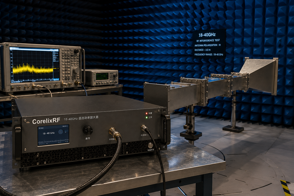
For a test bench, pay close attention to the DUT plane and the weakest required frequency point. For communication validation, focus on waveform linearity and backoff. For controlled interference testing, define the authorized test point, load environment and protection behavior. For aerospace subsystem validation, make the configuration and acceptance trail explicit. For an SDR-amplifier-antenna chain, review the source, amplifier, transitions and load as one system.
Once those conditions are clear, the wattage class becomes useful. Before that, it is only a label.
Send CorelixRF the RF chain, not just a wattage
For an engineering review, provide the operating range, signal type, power definition, output reference plane, path-loss estimate, source capability, RF interface, installation constraints, control requirements, quantity, destination and required documents.
Use the 18–40 GHz RF power amplifier product page to request applicable model data or a configuration review. If the project is still comparing frequency families, start with CorelixRF’s high-frequency RF amplifier capability.