
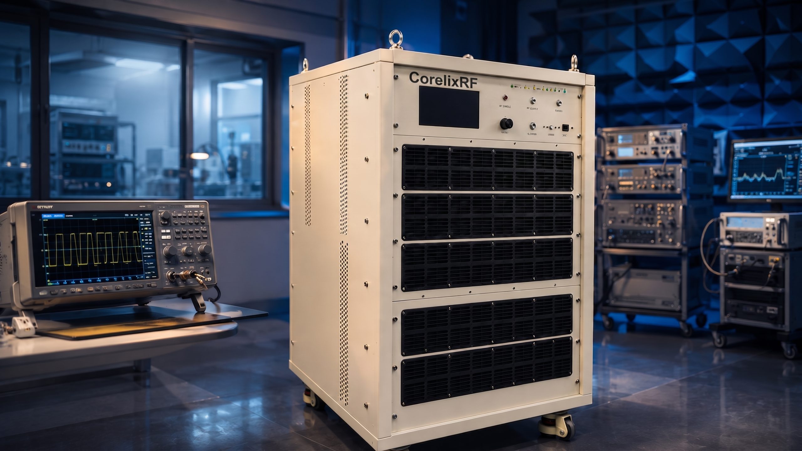
This commissioning log is for the CorelixRF CRF-PA-400M1000M-1500W, a 400 MHz-1 GHz 1500W pulsed RF amplifier for high-power UHF test systems. The datasheet lists 400 to 1,000 MHz frequency coverage, 1500 W pulsed output power, 1-50 us typical pulse width, 5% duty cycle, 62 dB minimum gain, 20 dB maximum gain control, N-Female rear-panel RF input and output, RS485/LAN control, AC 220 V input, forced-air cooling, and a 19-inch 6U rack-mount structure.
A commissioning log differs from a buying guide. It follows the order in which the amplifier becomes ready for use: receiving, rack fit, RF path, pulse definition, source lockout, monitoring, first low-power test, and release for repeatable operation. That sequence is useful for labs working on communication systems, RF interference or EW testing, aerospace control, and high-power UHF validation.
Change Trigger 1: The Rack Location Changes
Record the exact model name, purchase reference, included options, supplied drawing, and test data before the amplifier is moved into the rack. The unit is listed as a 19-inch 6U rack-mount amplifier with 70 kg weight, so handling should be planned. Receiving should also confirm that the N-Female RF input and output are protected and that rear-panel access is suitable for the rack location.
If the application needs a lower-power or CW path instead of pulsed power, compare the requirement against CorelixRF’s UHF RF amplifier options before assuming this 1500 W pulsed platform is the best starting point.
Change Trigger 2: Pulse Settings Change
The source data lists 1-50 us pulse width and 5% duty cycle. The commissioning record should state the first test pulse width, duty cycle, repetition behavior, and whether the source or host controller owns timing. A high-power pulsed amplifier should not be energized until the source settings are saved and reviewed.
- Confirm pulse width, duty cycle, and repetition behavior.
- Set source power below the listed 5 dBm maximum input value.
- Verify the 50 ohm load or fixture before PA enable.
- Record current, temperature, alarm state, and output measurement method.
- Keep a written stop condition for mismatch, overdrive, or temperature alarms.
Change-control note: this playbook begins after the first approved setup exists. It tells the team when to pause, review, and partially retest. The emphasis is not commissioning chronology; it is keeping a validated 1500 W pulsed RF setup from drifting after installation.
Change Trigger 3: Airflow or Thermal Conditions Change
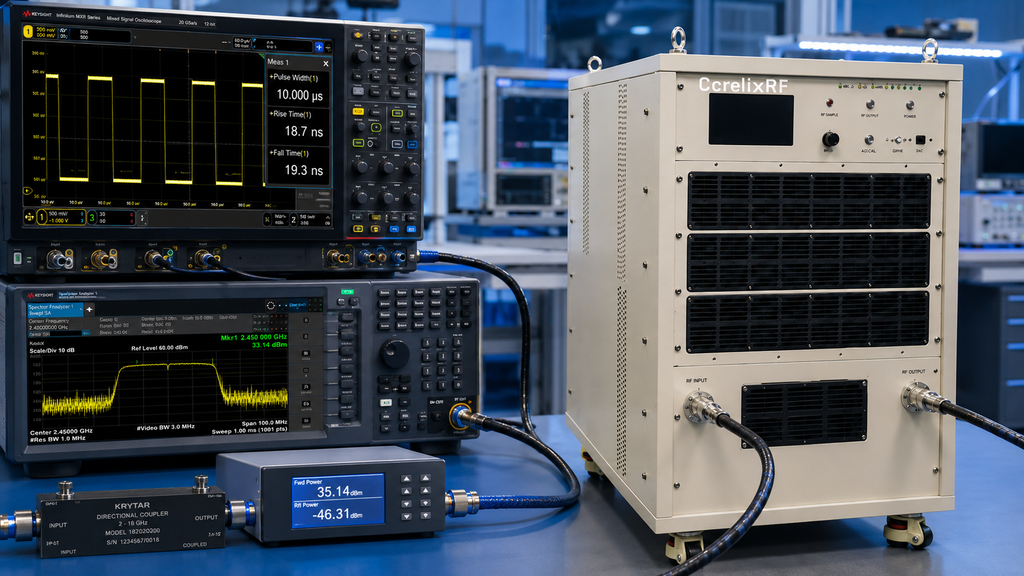
The amplifier uses forced-air cooling and a 6U rack structure. Commissioning should confirm inlet and outlet clearance, adjacent heat sources, service access, rack rail support, AC 220 V availability, and cable routing. The datasheet lists 400 W typical power consumption under the stated pulsed operating conditions, but the site should still review supply and thermal conditions for the actual test schedule.
A rack that passes a short functional test may still fail a long validation run if airflow is restricted. That is why the log should include ambient condition, run time, temperature trend, and whether any fans or filters need periodic maintenance.
Change Trigger 4: Monitoring Ownership Changes
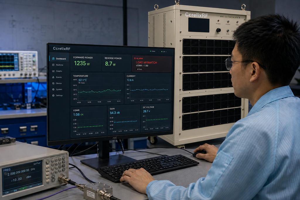
The model lists real-time temperature monitoring, real-time current monitoring, optional input power detection, optional forward/reverse power monitoring, alarm and fault protection, over-temperature protection, over-drive protection, load mismatch protection and alarm functions, and over-voltage protection. The commissioning owner should decide which values are displayed to the operator and which values are saved by the host system.
For automated racks, RS485/LAN control should be checked before high-power operation. If GPIB programmable control or additional monitoring is needed, it should be scoped through custom RF amplifier review before the final configuration is accepted.
Change Trigger 5: The Release Condition Is No Longer True
Release the amplifier for regular use only after the team has recorded pulse settings, source limits, RF load condition, connector path, gain setting, measured output, current, temperature, and alarm behavior. The log should identify who approved the setup and what changes would require retesting.
The release criteria should also define what is not covered. A different antenna, new coupler, changed pulse width, higher duty cycle, or software update can justify a partial recommissioning. That rule protects the amplifier and keeps the test record useful after the first installation.
For SEO and sales use, the strongest honest claim is practical: this is a high-power solid state power amplifier platform for 400 MHz to 1 GHz pulsed test systems, with configuration and documentation subject to project review. That is more credible than unsupported promises about availability or regulatory outcomes.
Change-Control Closeout
A useful commissioning log ends with the exact condition that is approved for regular use. Write the approved pulse width, duty cycle, source level, gain-control state, load, rack location, cooling condition, control mode, and operator response to alarms. The log should also list the evidence that supports release, including measured output data and current or temperature behavior during the checkout run.
The closeout should define change triggers. Moving the amplifier, replacing the load, changing pulse width, increasing duty cycle, updating control software, or adding a new RF switch should trigger a partial review. This prevents the 1500 W pulsed system from drifting away from the validated setup and gives maintenance teams a practical rule for when to retest.
Finally, store the commissioning log with the amplifier record rather than only in a project chat or operator notebook. Future users need to see the approved operating condition, not reconstruct it from memory. That habit is especially useful for shared UHF and EW benches where the same rack may support several programs over time.
FAQ
What frequency range does this UHF pulsed amplifier cover?
It covers 400 MHz to 1 GHz.
What pulsed output power is listed?
The datasheet lists 1500 W pulsed output power.
What pulse width and duty cycle are listed?
The source data lists 1-50 us typical pulse width with 5% duty cycle.
What mechanical format is listed?
The model is listed as a 19-inch 6U rack-mount amplifier with forced-air cooling.