
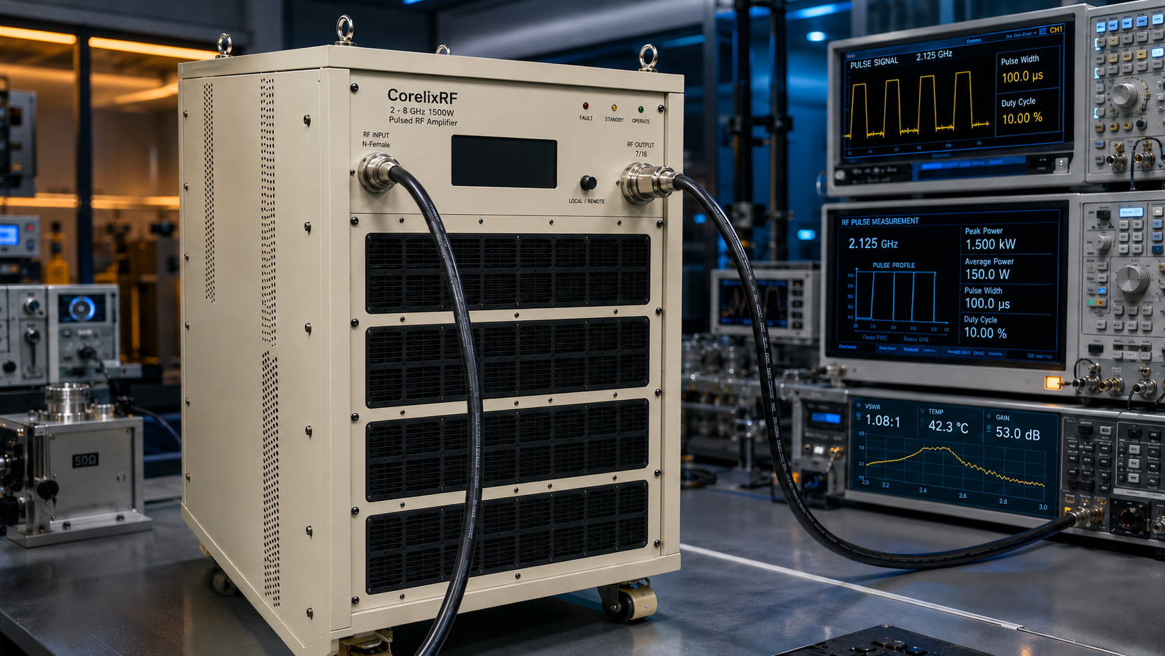
A 2-8 GHz 1500W pulsed RF amplifier should be specified around pulse behavior before rack layout is finalized. The CorelixRF CRF-PA-2000M8000M-1500W covers 2,000 to 8,000 MHz with 1500 W pulsed RF output power, 1-50 us pulse width, 10% duty cycle, 62 dB minimum small-signal gain, N-Female input, 7/16 output, RS485/LAN control, AC 220 V input, and air cooling.
This article uses a timing audit format because pulsed amplifier mistakes usually begin with unclear waveform assumptions. Engineers and purchasing teams need to define pulse width, duty cycle, repetition behavior, input drive, measurement method, remote-control logging, and load condition before the RFQ is released.
Training Module 1: Understand the Pulse Condition
The datasheet lists 1-50 us pulse width and 10% duty cycle. The RFQ should state the actual pulse width range, expected duty condition, whether timing is fixed or programmable, and how much margin is needed for future test modes. A generic request for a “1500W RF amplifier” is not enough for pulsed operation.
For radar simulation, EW testing, communication stress testing, or component validation, the pulse definition should be attached to the purchase file. If the waveform is generated by an SDR or external pulse source, review the source path with CorelixRF’s SDR amplifier integration guidance before setting drive limits.
Training Module 2: Respect the Input Drive Boundary
The listed maximum input power is 0 dBm. With 62 dB minimum gain, the amplifier should not be driven by an unlocked source. The first-power procedure should verify the 50 ohm input path, output load, gain-control setting, and source interlock before RF enable. Source limits should be written into the test procedure, not left to operator memory.
- Confirm pulse width and duty cycle before RF output tests.
- Lock source power below the specified maximum input level.
- Use a load and measurement path rated for pulsed output.
- Record gain setting, current, temperature, and alarm state.
- Stop testing when reflected-power or timing behavior changes unexpectedly.
Training Module 3: Read Pulsed Power Correctly
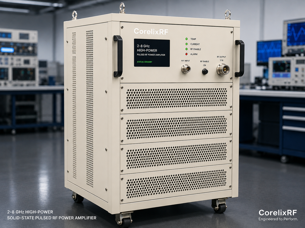
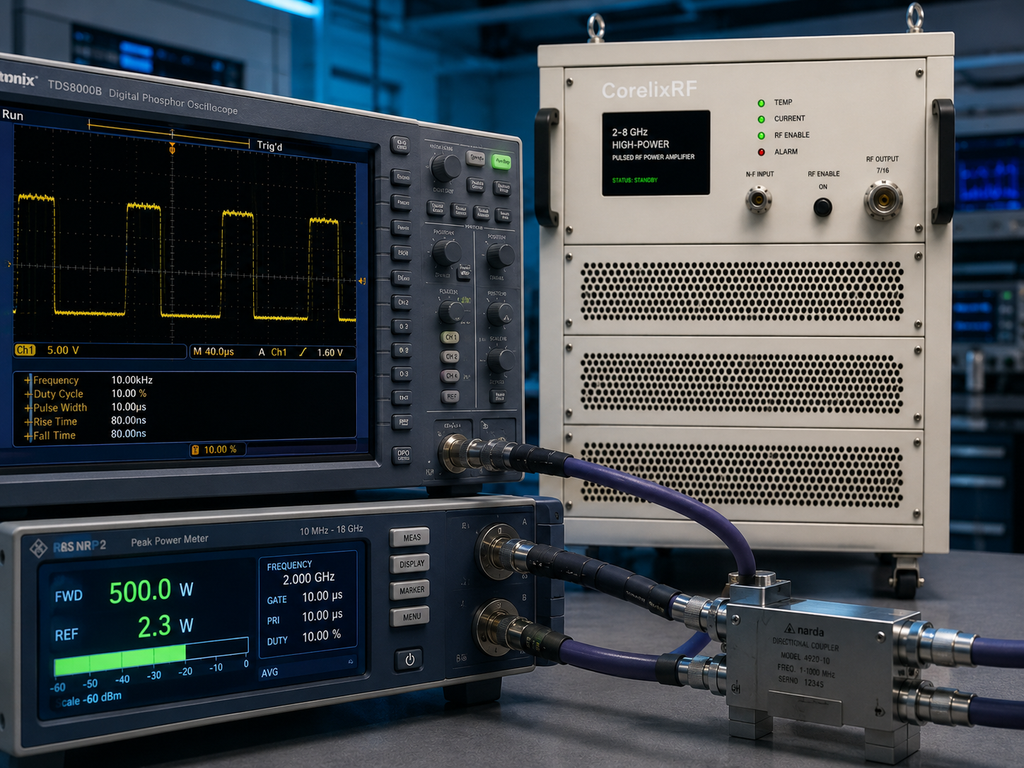
Pulsed output measurement is not the same as CW power measurement. The acceptance plan should specify detector, power meter, coupler, averaging mode, trigger timing, and calibration plane. The 7/16 output connector should be treated as a high-power interface, with adapters and couplers selected for the real pulse condition.
The datasheet lists -4 dB to +4 dB gain flatness, -15 dBc harmonics, and -60 dBc spurious performance. Final acceptance should use data from the delivered configuration and the measurement method agreed before shipment.
Training Module 4: Wait for Mechanical Release
Mechanical form factor is marked TBD in the source data. That means rack layout, weight handling, airflow clearance, and cable routing should remain open until the final drawing is provided. Do not issue a final rack drawing around an assumed enclosure size.
If the installation has strict space limits, the safer approach is to ask for custom RF amplifier review early. Customization may involve monitoring, control protocol, mechanical format, or documentation, depending on the project.
Training Module 5: Respond to Faults Without Guesswork
The model lists real-time temperature monitoring, real-time current monitoring, optional forward/reverse power monitoring, optional input power detection, alarm and fault protection, temperature monitoring and alarm, current monitoring and alarm, LAN remote control options, and project-specific protocol support. A pulsed test rack should log more than pass or fail; it should record the operating condition that produced the result.
This makes the amplifier easier to support later. If a fault appears during a long test, the log can show whether the cause was input overdrive, duty-cycle change, load mismatch, or thermal behavior. That traceability is valuable for engineering, purchasing, and supplier review.
When published as SEO content, keep the claim narrow: this is a GaN pulsed SSPA platform for high-power 2-8 GHz test systems, subject to final production test and project-specific configuration. Avoid unsupported claims about stock, certification, or customer deployments.
Operator Training Closeout
The timing audit should end with a signed table rather than a loose email thread. The table should capture pulse width, duty cycle, source model, trigger source, input drive limit, gain setting, output measurement method, coupler or load rating, control interface, and alarm response. A procurement team can attach that table to the RFQ so the technical requirement stays visible during quotation.
If the rack is expected to support several pulse modes, separate the required mode from future modes. The required mode should drive acceptance. Future modes should be labeled as review items. That distinction helps CorelixRF determine whether a standard pulsed RF power amplifier configuration is appropriate or whether a project-specific control, cooling, or monitoring package needs to be discussed.
The audit should also identify who owns timing changes after delivery. If software engineers can change pulse settings without RF approval, the rack can drift outside the validated condition. A simple release rule can prevent that: every new pulse width, duty cycle, or trigger mode receives an engineering signoff before high-power testing resumes.
That final signoff should be stored with the acceptance record for future audits.
FAQ
What pulse output power is listed?
The datasheet lists 1500 W pulsed RF output power.
What pulse conditions are listed?
The source data lists 1-50 us pulse width and 10% duty cycle.
What RF connectors are listed?
The input is N-Female and the output is 7/16.
Why is final mechanical data important?
The mechanical form factor is marked TBD, so the rack layout should wait for the final project drawing.