
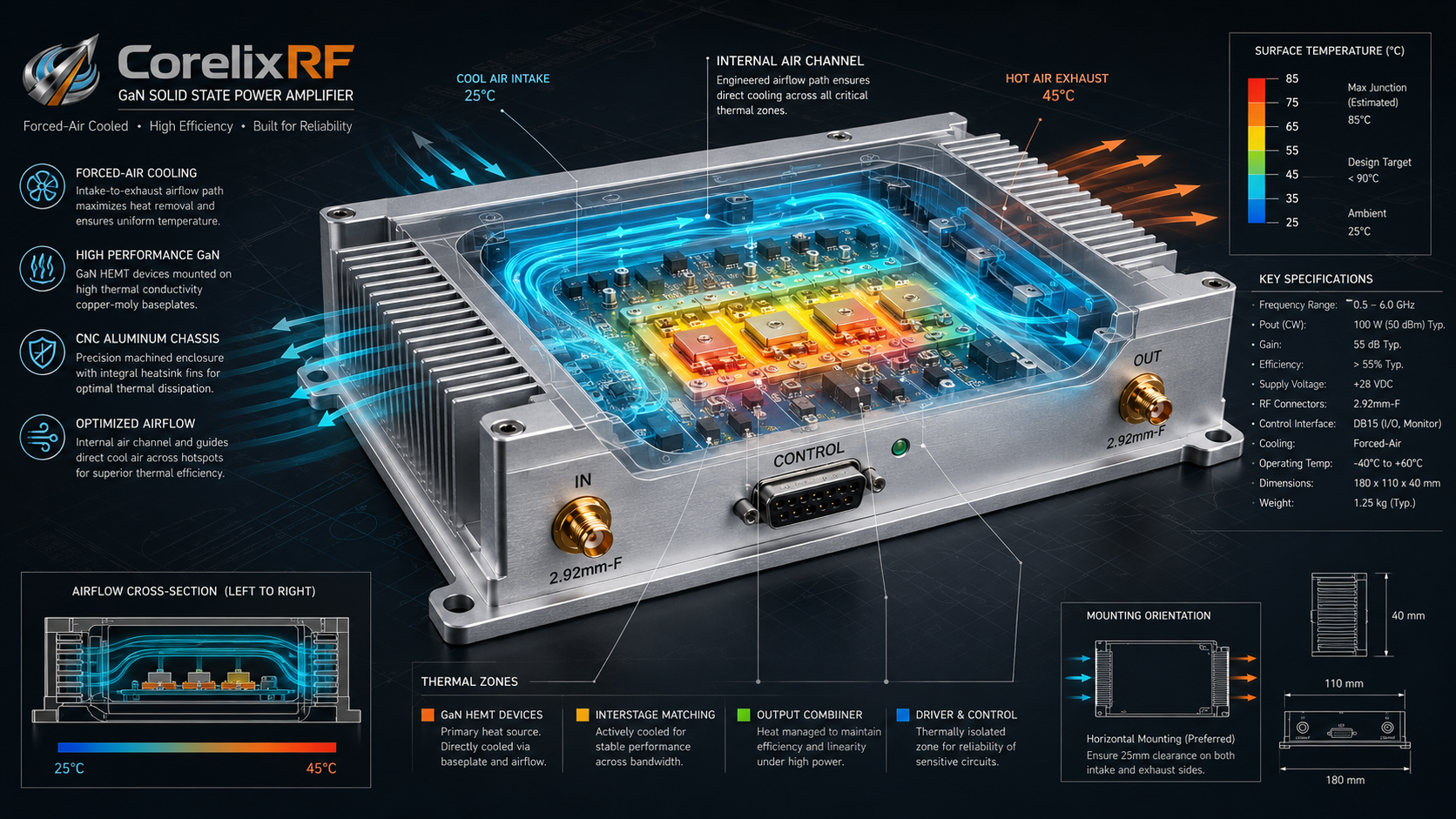
A 2-26.5 GHz 6W broadband RF amplifier is useful when an RF bench needs wide microwave coverage without moving directly into a rack-scale high-power system. The CorelixRF CRF-PA-2000M26500M-6W covers 2 GHz to 26.5 GHz, provides 6 W rated output power, lists 36 dB minimum small-signal gain, and uses 2.92 mm-F input and output connectors in a 240 x 160 x 50 mm forced-air module configuration.
This review is written for engineers integrating a compact GaN SSPA module into a microwave source chain, SDR-adjacent test path, RF interference bench, or aerospace-control validation setup. The search term “ultra wideband RF amplifier” often attracts buyers who want a single box to cover a large frequency range. The practical question is whether the module, source, cooling, control, and measurement plan can support the whole 2-26.5 GHz span.
Spec Decoder: 2-26.5 GHz Coverage
The amplifier covers more than a decade of frequency range. Cable loss, connector repeatability, source flatness, coupler response, load quality, and measurement uncertainty all change across the band. The datasheet lists -8 dB to +8 dB small-signal gain flatness, so the system should expect frequency-dependent drive or correction values.
If a project only uses part of the band, state that in the RFQ. A narrower operating window can change acceptance points, calibration effort, and whether a standard microwave amplifier path or custom configuration is more practical.
Spec Decoder: 2.92 mm-F Input and Output
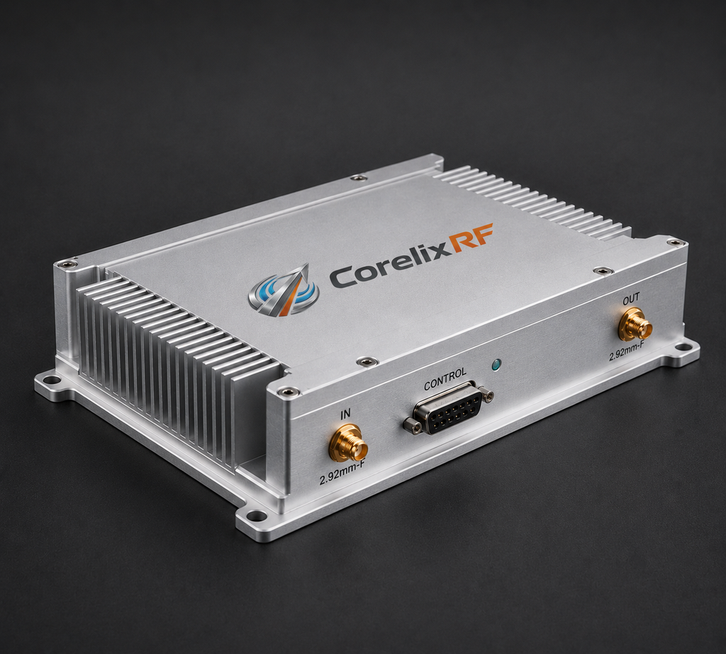
The listed RF input and output connectors are 2.92 mm-F. At 26.5 GHz, connector care is part of performance. Use compatible adapters, avoid worn hardware, inspect mating surfaces, and document the calibration plane. A small connector problem can look like poor amplifier behavior when the real issue is the fixture.
- Use torque and connector-care practices appropriate for 2.92 mm hardware.
- Keep the input source within the planned drive range for the selected gain state.
- Record cable and adapter changes between frequency sweeps.
- Validate load rating and return loss across the operating band.
- Store the final module drawing with the bench setup file.
Spec Decoder: Forced-Air Module Cooling
The module uses forced-air cooling and operates from 0 deg C to +40 deg C. Because the form factor is compact, the integrator owns the airflow environment. Enclosure vents, fan direction, heat recirculation, nearby modules, and dust control should be defined before long-duration testing.
A forced-air module in a tight chassis may need more review than a rack unit because the final thermal path depends on the host enclosure. If the amplifier will be embedded in an OEM system, discuss mechanical constraints through custom RF development rather than assuming the lab-bench airflow will match the production installation.
Spec Decoder: RS232 Control and Diagnostics
The datasheet lists RS232 control, real-time temperature monitoring, real-time current monitoring, optional forward/reverse power monitoring, alarm and fault protection, over-temperature protection, over-drive protection, over-voltage protection, and VSWR protection and alarm functions. The control plan should identify whether RS232 is used only for setup or also for automated test logging.
For wideband validation, logging matters because results can vary with frequency, gain-control state, and fixture. The host should record command state, current, temperature, output-power measurement, and any fault events. That turns a one-time test into repeatable engineering data.
Spec Decoder: RFQ Data Becomes the Real Specification
A strong RFQ for this SDR RF amplifier or microwave source-chain module should include frequency range, output power target, waveform type, source power, connector plan, enclosure airflow, control interface, monitoring needs, and the expected acceptance data. The datasheet lists CE/RoHS documentation support where applicable and project-based regulatory documentation support upon request, but the final documentation depends on configuration, market, and use case.
The model is a good topic for buyers who need broad coverage at moderate power. It should not be positioned as a replacement for every high-power rack amplifier. Its value is flexibility, compactness, and wide frequency coverage when the system design can handle calibration and thermal details.
Before procurement, decide whether the amplifier will live as a laboratory module, an OEM subassembly, or a temporary integration tool. Each role changes the mechanical drawing, cooling evidence, control documentation, and acceptance worksheet that should accompany the order.
Specification Decoder Closeout
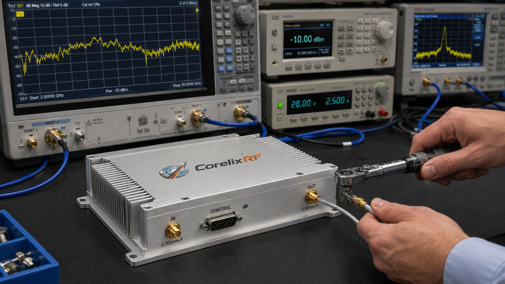
A compact wideband module should leave the engineering bench with a clear closeout file. Include the final mounting orientation, fan path, DC supply cable length, RS232 wiring, source-level limits, connector-care rule, and a sweep table that shows which frequency points were tested. Without that file, the next user may repeat the same setup work or misread fixture loss as amplifier variation.
For OEM use, the closeout file should also name the host-system assumptions. If the production enclosure changes airflow, cable length, control timing, or nearby heat sources, the amplifier should be retested under the new condition. That is especially important for a broadband RF amplifier because small changes can affect different parts of the band in different ways.
The review should also say how the module will be protected during routine bench changes. Label the 2.92 mm adapters, keep dust caps available, note the approved supply current limit, and store the control cable with the amplifier. These small controls reduce avoidable damage and keep the wideband bench ready for repeatable microwave measurements.
FAQ
What frequency range does this broadband amplifier cover?
It covers 2 GHz to 26.5 GHz.
What output power is listed?
The datasheet lists 6 W rated output power.
What RF connectors are used?
The listed input and output connectors are 2.92 mm-F.
What control interface is listed?
The datasheet lists RS232 control.