
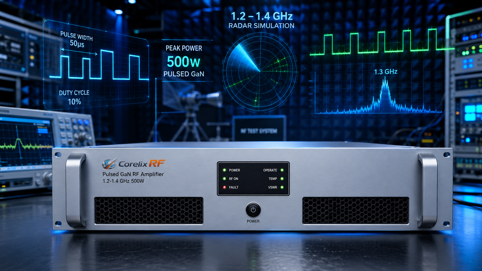
A 1.2-1.4 GHz 500W pulsed GaN RF amplifier must be specified around pulse behavior, not only frequency and peak power. The CorelixRF CRF-PA-1200M1400M-500W is a 3U rack-mount pulsed SSPA covering 1.2 GHz to 1.4 GHz with 500 W rated pulsed RF output power, 57 dB minimum gain, 50 us typical pulse width, 10% duty cycle, RS485/LAN control, forced-air cooling, and monitoring/protection functions.
The article structure follows the product-update and application-note model seen on Empower RF Systems’ website: define the use case, state the model and power class early, then explain features in the language of system integration, test confidence, and RFQ readiness. All technical details here are based on the CorelixRF datasheet.
Product Snapshot
The CRF-PA-1200M1400M-500W is a GaN pulsed SSPA platform for high-power RF systems. The datasheet lists 1200 MHz to 1400 MHz frequency coverage, 500 W pulsed output power, 57 dB minimum gain, -3 dB to +3 dB gain flatness, and up to 20 dB gain control.
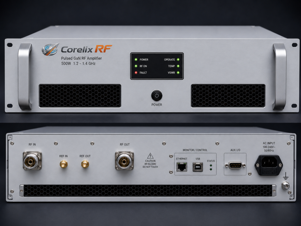
The pulsed operating condition is listed as 50 us typical pulse width with 10% duty cycle. Input power is listed at 2 dBm maximum. The RF input is SMA-Female on the rear panel, and the RF output is N-Female on the rear panel. The rack uses AC 220 V +/-10%, 50/60 Hz power through a single-phase IEC inlet.
Application Fit
This model is listed for test and measurement instrumentation, communication systems, RF interference/EW system-level testing, radar simulation and pulsed RF testing, and aerospace control systems. Those applications share one common requirement: the amplifier must deliver controlled pulsed RF power while giving the operator enough monitoring and protection to run repeatable tests.
If a buyer is comparing broader pulsed RF power amplifier options, the 1.2-1.4 GHz operating window should be stated clearly. A pulsed RFQ without frequency, pulse width, duty cycle, and control requirements is not complete.
Pulse Parameters Come First
For pulsed RF systems, average thermal stress depends on duty cycle, pulse width, repetition behavior, burst structure, and operating duration. A 500 W pulsed amplifier with a 50 us pulse and 10% duty cycle is not equivalent to a CW amplifier with the same headline power number.
Engineers should define pulse width, duty cycle, pulse repetition frequency, number of pulses per burst, operating duration, and required recovery time. If several pulse modes are used, list each one and identify the worst-case condition.
Rack Integration and Remote Control
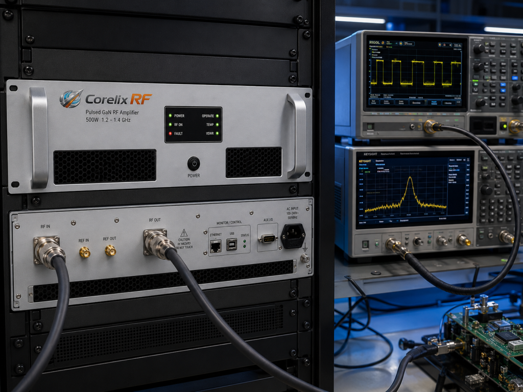
The CRF-PA-1200M1400M-500W is specified as a 3U rack-mount unit with forced-air cooling and 18 kg weight. For rack integration, confirm airflow direction, rear-panel connector access, rack depth, power availability, grounding, and RF cable routing.
RS485/LAN control makes the amplifier more suitable for automated test systems than a manually controlled power stage. Ask for the control protocol if the rack must be integrated into a test executive, remote console, or safety interlock system.
Monitoring and Protection
The datasheet lists real-time temperature monitoring, real-time current monitoring, optional forward/reverse power monitoring, optional LAN remote monitoring, alarm/fault protection, over-temperature protection, over-drive protection, over-voltage protection, and VSWR protection/alarm functions.
These functions should be part of the test plan. A radar simulation or pulsed test setup should define what happens when a VSWR alarm occurs, whether the system retries, and how the operator sees the fault state.
RFQ Checklist
Include frequency range, pulsed output power, pulse width, duty cycle, pulse repetition frequency, waveform, input drive limit, gain-control needs, RF connectors, control interface, rack power, airflow constraints, mismatch conditions, monitoring requirements, and expected documentation.
For projects that do not fit the standard model, request a custom RF amplifier review with timing diagrams and system block diagrams attached.
Test Setup Details That Reduce RFQ Risk
A pulsed amplifier RFQ should include the measurement setup as well as the amplifier target. State where output power is measured, what couplers or attenuators are in the path, how pulse power is captured, and whether the rack must communicate with an existing safety interlock or test executive. These details help separate amplifier performance questions from fixture, cable, load, and control-system issues.
FAQ
What frequency range does this pulsed amplifier cover?
The datasheet specifies 1.2 GHz to 1.4 GHz operation.
What pulsed output power is listed?
The model is listed at 500 W rated pulsed RF output power.
What pulse condition is specified?
The datasheet lists 50 us typical pulse width with 10% duty cycle.
Is remote control supported?
The datasheet lists RS485 / LAN control, with optional LAN remote monitoring.