
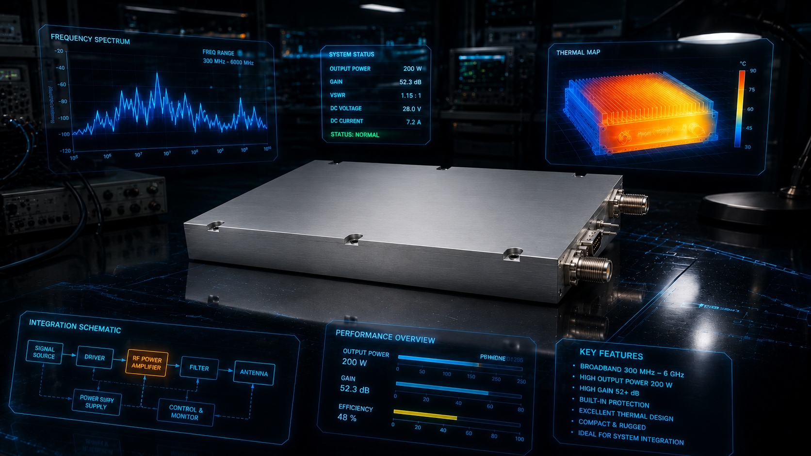
Selecting a broadband RF power amplifier is rarely just a question of finding the highest wattage number on a datasheet. In real RF labs and embedded systems, the amplifier must support the required frequency range, deliver useful output power across that range, remain stable with the expected signal environment, and fit the mechanical, thermal, and control needs of the project. Engineers and technical buyers also need a realistic path from bench evaluation to repeatable deployment.
For that reason, the best amplifier choice starts with a system-level review. The frequency band, modulation type, duty cycle, load conditions, connector preference, cooling method, protection features, and control interface all affect whether a unit is a good fit. A broadband amplifier that works well for swept testing may not be ideal for a high-duty-cycle communications system. A compact module that is convenient inside an enclosure may require more attention to airflow than a rackmount amplifier with integrated cooling.
CorelixRF supports RF power amplifier projects where bandwidth, integration, and application fit need to be considered together. The following checklist can help teams prepare a cleaner requirement before requesting an amplifier review.
Start With Frequency Coverage and Flatness
The first requirement is operating frequency. A broadband RF amplifier should cover the project band with margin, especially when the system uses swept signals, agile radios, harmonics filtering, or future waveform changes. It is useful to define the required continuous frequency range, the preferred operating range, and any areas where reduced output is acceptable.
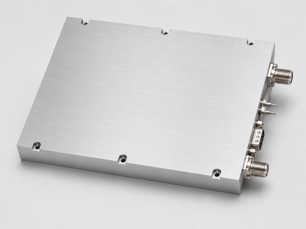
Gain flatness also matters. A wideband amplifier may have different gain and output capability at the low, mid, and high ends of the band. If the system depends on predictable field strength, receiver stimulus, or transmitter chain level, engineers should ask how the amplifier behaves across the full band rather than relying on a single nominal gain value.
Define Output Power in the Context of the Signal
Output power should be evaluated under realistic signal conditions. Continuous wave testing, pulsed operation, broadband noise, OFDM, and multi-tone signals can stress an amplifier differently. Average power, peak envelope power, duty cycle, and linearity expectations should be discussed early.
For many applications, the right question is not simply “how many watts?” It is “how much usable power is available across the frequency range with the waveform and duty cycle we intend to run?” That framing helps avoid underspecifying thermal load or overspecifying a costly amplifier that is larger than needed.
Consider Gain, Drive Level, and System Margin
Gain determines how much input power is required to reach the target output. If the signal source is an SDR, signal generator, upconverter, or exciter with limited output level, the amplifier must provide enough gain to meet the system goal. If the source has higher drive capability, input protection and gain control become more important.
It is also useful to leave margin. A chain that only works when every component is at its best-case value may be difficult to repeat in production or field operation. A practical requirement includes cable loss, filter loss, coupler loss, and the expected range of source output levels.
Review Interfaces, Monitoring, and Control
RF connectors are only part of the interface discussion. Engineers should also define DC input, AC power, enable control, alarm outputs, monitoring needs, and whether the amplifier will be used locally or controlled by a larger system. Some projects need simple front-panel operation. Others need remote enable, fault monitoring, or integration into automated test equipment.
For a custom RF amplifier request, sharing the intended control environment helps the supplier recommend a practical configuration. Details such as connector family, rackmount preference, module footprint, heat-sink approach, and expected cable routing can prevent late-stage mechanical changes.
Thermal Design Is a Requirement, Not an Accessory
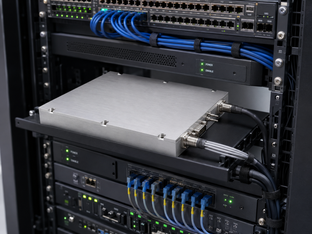
Broadband solid state amplifiers turn part of the input power into heat. Cooling must match the operating mode. A unit used for short bench tests may not face the same thermal load as one running high-duty-cycle waveforms in a closed cabinet. Ambient temperature, airflow direction, mounting orientation, and system backpressure all deserve attention.
Protection features can help guard the amplifier, but they do not replace good thermal design. Over-temperature protection, reflected-power protection, current limits, and fault reporting are most valuable when the installation also provides suitable cooling and load conditions.
Match the Amplifier to the Application
Different applications weight requirements differently. EMC and immunity testing often emphasize reliable power delivery into changing load environments. SDR amplifier chains may emphasize gain, bandwidth, and signal fidelity. Manufacturing test systems may prioritize repeatability, control, and serviceability. Research benches may need flexible bandwidth and connector convenience.
Before selecting a unit, write the requirement as a complete use case: frequency, output target, waveform, duty cycle, input source, load or antenna, cooling environment, connector needs, control method, and desired delivery form. This makes the amplifier review faster and reduces back-and-forth.
When to Request a Custom Review
If the project has unusual frequency coverage, tight mechanical limits, special control requirements, high duty cycle, or challenging load conditions, a standard part-number comparison may not be enough. A review with CorelixRF can help map the requirement to an appropriate solid state RF amplifier approach or identify where customization is needed.
Teams preparing an RF amplifier project should include the target band, output power goal, available drive level, signal type, duty cycle, supply or AC power preference, connector requirements, enclosure constraints, and expected operating environment.
FAQ
What is a broadband RF power amplifier?
A broadband RF power amplifier is designed to amplify RF signals across a relatively wide frequency range instead of a narrow tuned band. It is commonly used in test systems, communications research, EMC-related setups, and multi-band RF integration.
How much output power should I specify?
Specify output power in relation to the waveform, duty cycle, frequency range, and required system margin. Average power, peak power, and linearity expectations may all matter depending on the application.
Why is gain flatness important?
Gain flatness affects how predictable the amplifier output is across frequency. If output level consistency matters, engineers should evaluate gain and power behavior across the full operating band.
Can a broadband RF amplifier be customized?
Many projects benefit from customization around frequency range, packaging, control, connectors, cooling, or protection behavior. Share the full integration requirement when requesting a review.
Does the amplifier need external cooling?
Cooling depends on the product design and operating mode. Always review thermal requirements, airflow, duty cycle, and installation conditions before finalizing the amplifier configuration.