
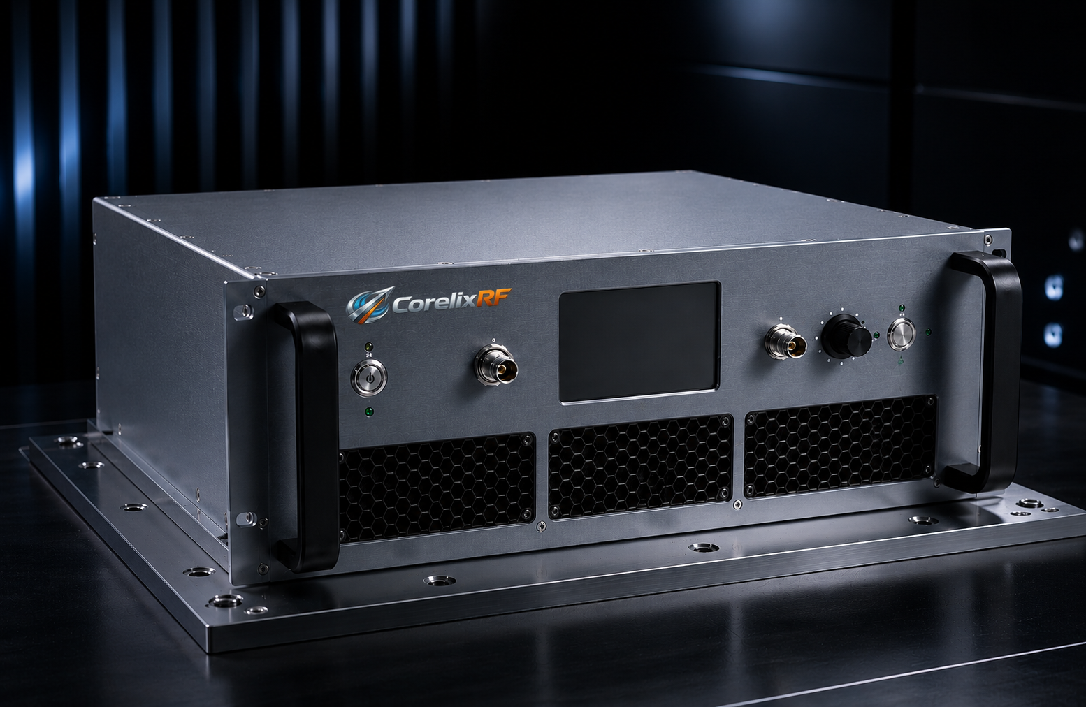
A 2-18 GHz RF amplifier is useful when a test system or RF platform needs microwave coverage across multiple bands instead of a narrow single-frequency design. This range can support lab validation, swept-frequency testing, wideband receiver stimulus, EW-related research environments, component evaluation, and other engineering workflows where flexibility is important. Because the frequency span is broad, the amplifier requirement should be written carefully before selecting a product or requesting customization.
The 2-18 GHz range places more pressure on connector selection, gain behavior, output power variation, thermal design, and measurement setup than lower-frequency narrowband systems. A clean requirement helps the amplifier supplier understand whether the project needs maximum bandwidth, high output level, compact integration, linear operation, rugged protection, or a balanced combination of these priorities.
CorelixRF can review wideband RF amplifier requirements and help engineering teams evaluate the practical tradeoffs behind a microwave amplifier choice. The best starting point is a complete description of how the amplifier will be used.
Why 2-18 GHz Coverage Needs Careful Definition
The phrase “2-18 GHz” sounds simple, but it covers a large microwave span. Performance will not always be identical at every point in the band. Gain, saturated output power, small-signal response, harmonic behavior, and thermal load can vary across frequency. Engineers should define the most critical parts of the band, the minimum acceptable output power, and whether performance must be continuous across the full range.
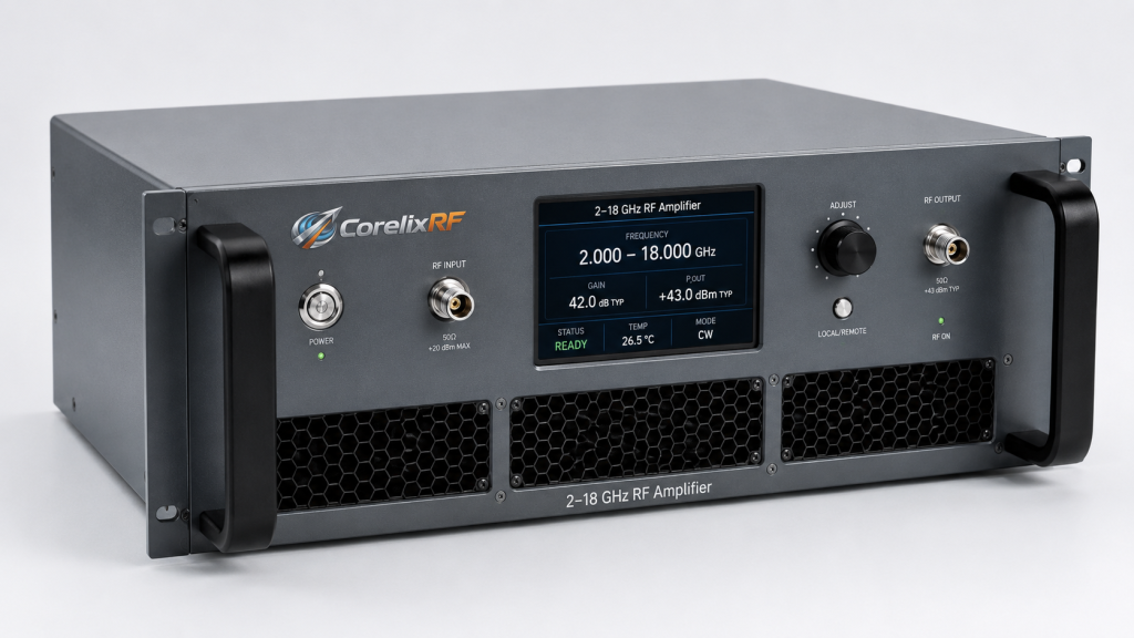
If the system only uses specific sub-bands, state them clearly. If the amplifier must support unknown future bands, explain that as well. This distinction affects whether a standard wideband approach is sufficient or whether a project-specific recommendation is more appropriate.
Output Power and Linearity Are Application Dependent
Microwave amplifier output power should be tied to the application. A swept CW test bench may focus on power delivery at specific frequencies. A communications waveform may require linearity and headroom. A multi-tone or noise-like signal may stress the amplifier differently than a single-tone signal. For SDR-based systems, the peak-to-average ratio can be especially important.
When preparing a request, include the waveform type, expected average power, peak needs if known, and duty cycle. If linearity is important, explain the acceptable distortion or system-level metric instead of only listing a wattage target.
Gain and Drive Level Must Match the Source
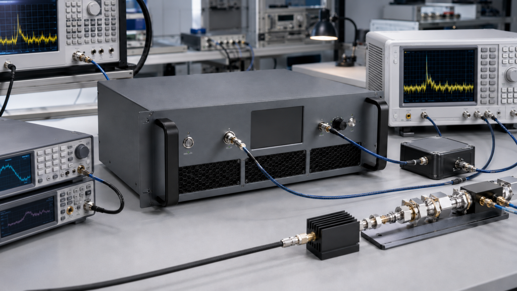
Many microwave test systems use signal generators, synthesizers, upconverters, or SDR outputs as the drive source. These sources may not provide enough power to drive every amplifier to the desired output level. The amplifier gain must therefore be matched to the available drive power and the losses between the source and amplifier input.
If external attenuators, switches, filters, or long cables are used, include those losses. A system that looks adequate on paper can miss its output goal if the drive chain is not included in the calculation.
Connectors, Cables, and Layout Matter at Microwave Frequencies
At 2-18 GHz, RF connector choice and cable quality become major system details. Connector family, torque practice, adapter count, and cable loss can all affect repeatability. If the amplifier will be installed in a rack, enclosure, or mobile platform, cable routing and connector access should be reviewed before the mechanical design is frozen.
A wideband microwave amplifier can only perform as well as the surrounding RF path allows. Keeping the RF chain short, controlled, and well documented helps protect measurement quality.
Thermal and Protection Requirements
Solid state microwave amplifiers require appropriate cooling. Duty cycle, ambient temperature, enclosure airflow, and load mismatch exposure influence thermal design. Systems that operate for long test runs need more careful thermal planning than quick bench experiments.
Protection features such as over-temperature shutdown, reflected-power protection, or fault reporting should be considered when the load may change or when the amplifier is integrated into automated equipment. These features support reliability, but they should be paired with proper airflow and operating discipline.
Integration Checklist for Buyers and Engineers
Before requesting a quote or review, gather the required frequency range, critical sub-bands, output power target, waveform, duty cycle, drive level, connector preference, cooling environment, control needs, mechanical constraints, and any safety or fault-reporting requirements. This information helps determine whether a standard microwave power amplifier approach is suitable.
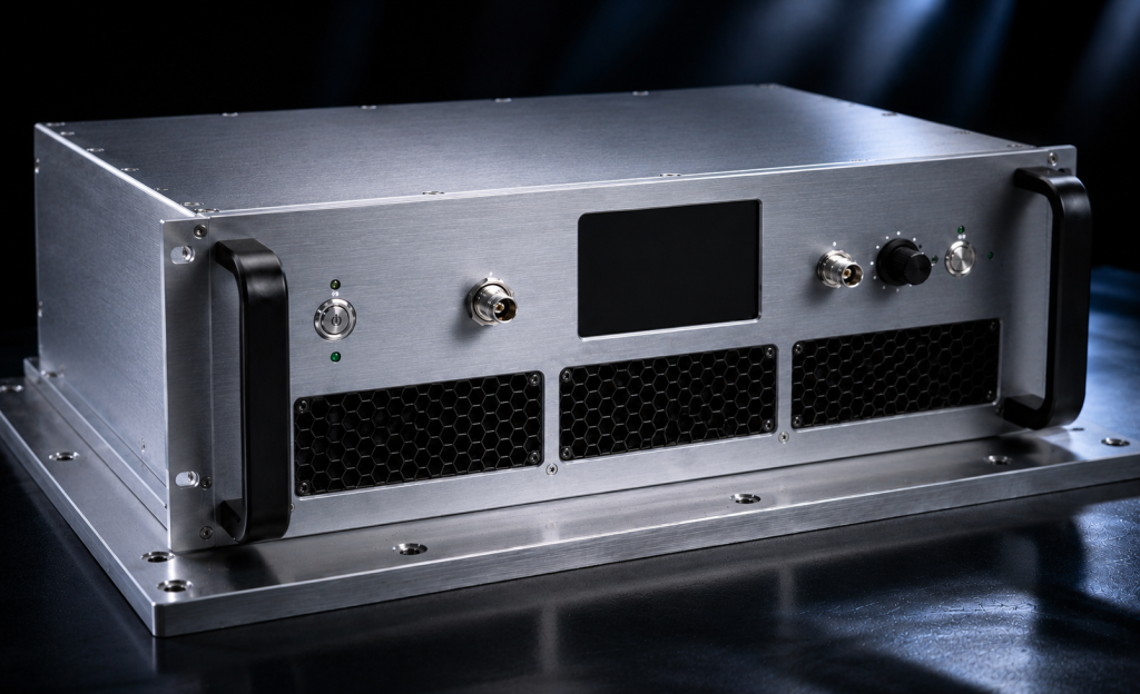
If the system has unusual requirements, a custom RF amplifier review can reduce risk before procurement. It is better to resolve frequency, power, and thermal assumptions early than to redesign the RF chain after installation.
FAQ
What is a 2-18 GHz RF amplifier used for?
It is commonly used where wide microwave coverage is needed, including test benches, swept-frequency work, SDR chains, receiver testing, component evaluation, and integrated RF systems.
Is output power constant from 2 to 18 GHz?
Not necessarily. Wideband amplifier performance can vary across frequency, so engineers should review minimum power requirements across the full operating range or critical sub-bands.
What information is needed for a 2-18 GHz amplifier quote?
Useful details include frequency range, output target, waveform, duty cycle, drive level, connectors, cooling environment, enclosure limits, and control or monitoring needs.
Can a 2-18 GHz amplifier be used with an SDR?
It may be suitable when gain, drive level, linearity, filtering, and thermal requirements are matched to the SDR system. The full signal chain should be reviewed.
Why are connectors important at 2-18 GHz?
Connector quality, adapter count, torque, and cable loss can affect repeatability and power delivery at microwave frequencies.