
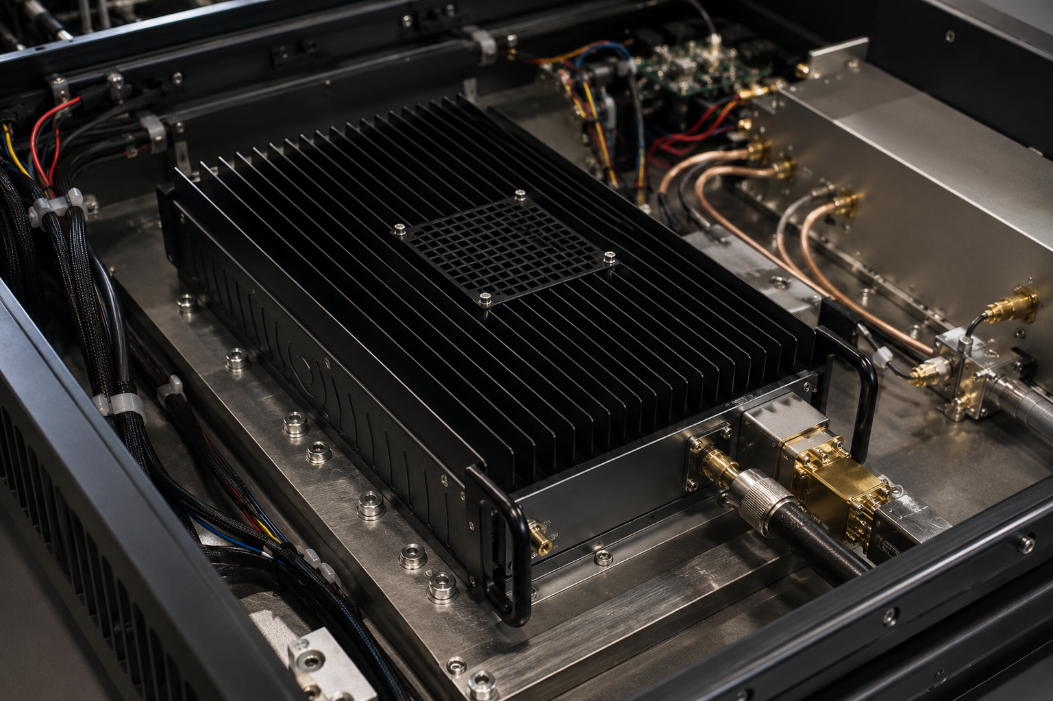
The CRF-PA-40G67G-5W model direction addresses a difficult part of RF engineering: 40-67 GHz mmWave test and integration. At this frequency range, every detail around the amplifier matters. Connector selection, waveguide or coax transitions, cable loss, fixture repeatability, calibration plane, thermal path, and handling procedure can affect measured performance. A 5W-class amplifier in this band should be specified with the full test setup in mind.
CorelixRF’s RF power amplifier platforms provide the broader product context for high-frequency and custom RF amplifier review. Engineers already working with 18-40 GHz RF power amplifier platforms may need to extend into a higher 40-67 GHz path when the application moves toward V-band or upper mmWave testing.
Why 40-67 GHz Is a Different Integration Problem
A 40-67 GHz RF amplifier works in a range where bench loss and repeatability can dominate the system result. A small adapter change, connector wear, torque difference, or cable movement can change measurements. The amplifier model should therefore be evaluated together with the test fixture, cables, transitions, and calibration method.
Before requesting CRF-PA-40G67G-5W, define whether the project requires full 40-67 GHz coverage or only a narrower operating window. If the system uses fixed channels, list them. If it sweeps, include sweep plan and dwell time. If the signal is modulated, include bandwidth and output-quality expectations.
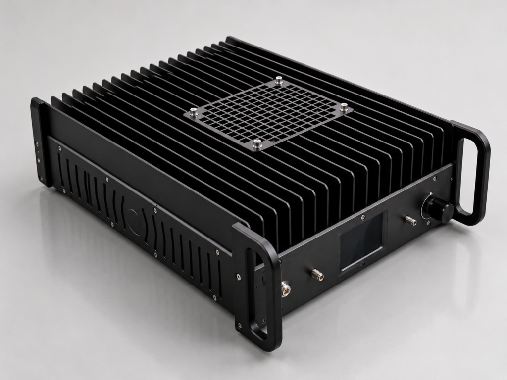
Put the 5W Target in System Context
A 5W mmWave amplifier may be substantial at this frequency range, but the relevant question is where that 5 W must be available. Power at the amplifier connector is different from power after transitions, cables, couplers, or fixtures. State the reference plane clearly.
If the model feeds an antenna, waveguide structure, or device under test, include downstream loss and mismatch assumptions. If the system is measurement-focused, define the calibration method and whether the amplifier output is characterized alone or as part of a larger path.
Connector and Fixture Discipline
For a V-band RF power amplifier, interface discipline is not optional. Connector type, adapter count, torque procedure, cable support, and fixture stability all affect repeatability. Include connector preferences and any required transitions in the RFQ. If the system has a fixed mechanical package, provide drawings early.
This also helps with troubleshooting. When the bench is designed consistently, the team can distinguish amplifier behavior from fixture and connector variation more effectively.
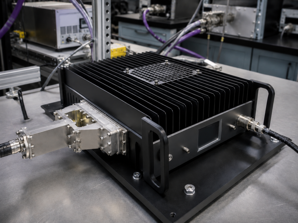
Cooling, Supply, and Mechanical Fit
Even a compact high frequency amplifier module needs a controlled thermal path. State expected operating duration, ambient temperature, duty cycle, mounting surface, airflow, and enclosure constraints. If the amplifier is part of an OEM instrument, include supply voltage limits, service access, controller requirements, and documentation needs.
The right review process should connect RF performance with mechanical and thermal reality. That is especially important above 40 GHz, where late-stage packaging changes can also affect the RF path.
FAQ
What is CRF-PA-40G67G-5W used for?
It is suitable for review in 40-67 GHz mmWave testing, V-band research, high-frequency component evaluation, antenna paths, and OEM test equipment.
Why is calibration important at 40-67 GHz?
Loss and repeatability challenges increase at mmWave frequencies. Calibration defines whether power is evaluated at the amplifier output, fixture, antenna, or DUT plane.
What should I include in the RFQ?
Include frequency range, power reference plane, waveform, input level, cables, connectors, transitions, load, cooling, mechanical limits, and documentation expectations.
Can CorelixRF review custom mmWave requirements?
Yes. CorelixRF can review high-frequency RF amplifier requirements involving non-standard frequency, interface, cooling, mechanical structure, and system integration.