
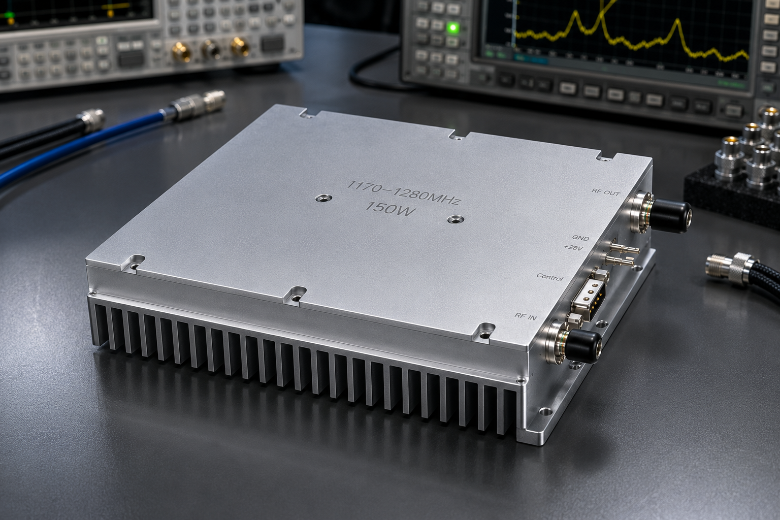
A 1170-1280 MHz 150W GaN RF amplifier is a practical fit when an RF system needs a controlled, narrowband high-power stage rather than a general-purpose broadband module. The CorelixRF CRF-PA-1170M1280M-150W is specified for 1170 MHz to 1280 MHz operation with 150 W rated CW output power, a third-generation GaN SSPA design, gain adjustment, optional RS485 monitoring/control, optional VCO source configuration, and protection functions for integration work.
This article follows a product-update and application-note structure similar to the way Empower RF Systems often frames technical content: identify the application problem, summarize the amplifier platform, list the engineering highlights, then explain integration details that affect a real purchase decision. The point is not to copy a competitor; it is to make the CorelixRF specification easier for engineers and purchasing teams to evaluate.
Product Snapshot
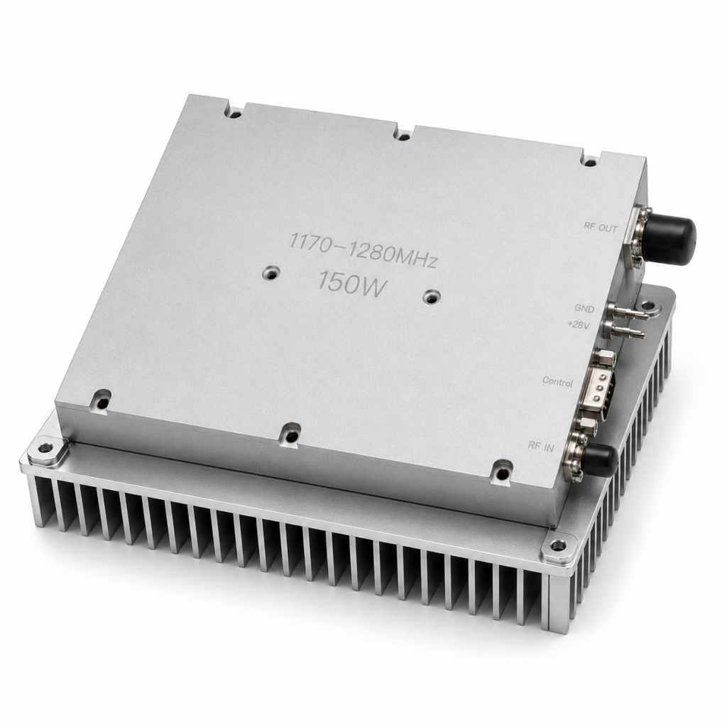
The CRF-PA-1170M1280M-150W is a solid-state narrowband RF power amplifier for RF source integration, communication systems, and test and measurement setups. The datasheet lists 1170-1280 MHz frequency coverage, 120 W minimum saturated output power, 150 W rated output power, and 48 dB minimum, 50 dB typical, 52 dB maximum gain.
The module uses a +28 V DC nominal supply with an allowed 24 V to 32 V operating range. Typical current is listed at 22 A, with a maximum value of 27 A. The form factor is 200 x 158 x 25 mm with approximately 1.4 kg weight and external heat-sink cooling. These are important details for buyers who need to fit the amplifier into an existing chassis or source assembly.
Where This Narrowband Amplifier Fits
A narrowband amplifier is useful when the system needs power and control over a known operating window. Instead of paying for unnecessary octave coverage, engineers can focus on output power, gain stability, thermal design, control wiring, and protection behavior across 1170 MHz to 1280 MHz.
Typical use cases include narrowband RF amplification, communication-system testing, RF test and measurement, and project-specific RF source integration. Teams comparing wider RF power amplifier platforms should treat this model as a more focused option when the frequency plan is already defined.
Key Capabilities Engineers Should Review
The datasheet highlights a 20 dB gain adjustment range with 0.5 dB step control. That matters when the amplifier must be calibrated into a signal chain instead of simply driven at one fixed level. The M version operates as an amplifier module without internal VCO, while the V version supports an internal VCO source with 10 Hz stepping. That creates two different integration paths: external-source amplification or integrated source/amplifier configuration.
For control and diagnostics, the specification calls out optional RS485 monitoring/control, PA enable/disable control, forward and reverse power indicators, temperature analog output, and alarm reset support where applicable. These details are often what turn a lab amplifier into a usable OEM subsystem.
Interface and Thermal Planning
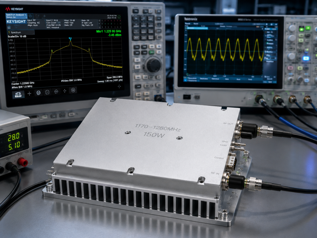
The RF connector reference is SMA-KFD46 for RF input and output on applicable configurations. Control is through a D-Sub 15-pin female interface, while power input uses a pull-core capacitance connector. Before purchase, engineers should request the final mechanical drawing and confirm connector orientation, mounting holes, cable bend radius, and heat-sink contact area.
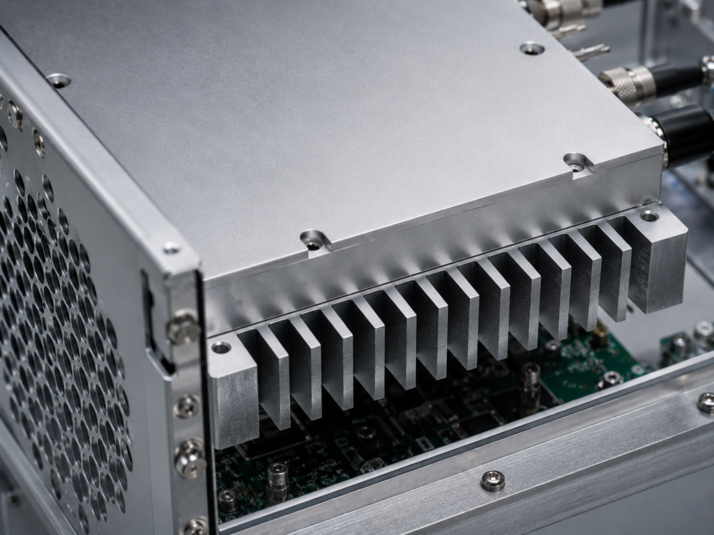
External heat-sink cooling is not a minor note. A 150 W CW amplifier can only be reviewed properly when the thermal path, airflow, ambient temperature, duty condition, and chassis mounting surface are known. CorelixRF’s custom RF amplifier review path is the right place to provide those installation constraints.
Protection and Monitoring
The CRF-PA-1170M1280M-150W lists over-temperature shutdown/recovery, over-VSWR locked shutdown, over-voltage lock above 32 V, and over-current lock above 29 A. Those protection functions help reduce integration risk, but they should still be mapped into the system controller. A fault that protects the amplifier also needs to be visible to the operator or host system.
If the system is used in a repeated production test sequence, ask for the control protocol, alarm reset behavior, and power indicator scaling. That information helps software and hardware teams avoid late-stage debugging.
What to Include in the RFQ
A clear RFQ should state frequency range, required output power at the load, waveform type, expected input drive level, gain-control needs, supply limits, heat-sink or airflow plan, connector preferences, monitoring requirements, and whether the VCO configuration is needed. If the amplifier is part of a broader UHF power amplifier program, include system diagrams and operating scenarios rather than a single power target.
FAQ
Is the CRF-PA-1170M1280M-150W a broadband amplifier?
No. It is a narrowband GaN SSPA specified for 1170 MHz to 1280 MHz operation.
What output power is listed?
The datasheet lists 150 W rated CW output power, with 120 W minimum saturated output power.
Does the amplifier support remote control?
Optional RS485 monitoring/control is listed, along with PA enable/disable and diagnostic outputs where applicable.
What cooling approach is required?
The model uses external heat-sink cooling, so the mechanical and thermal path should be reviewed before integration.