
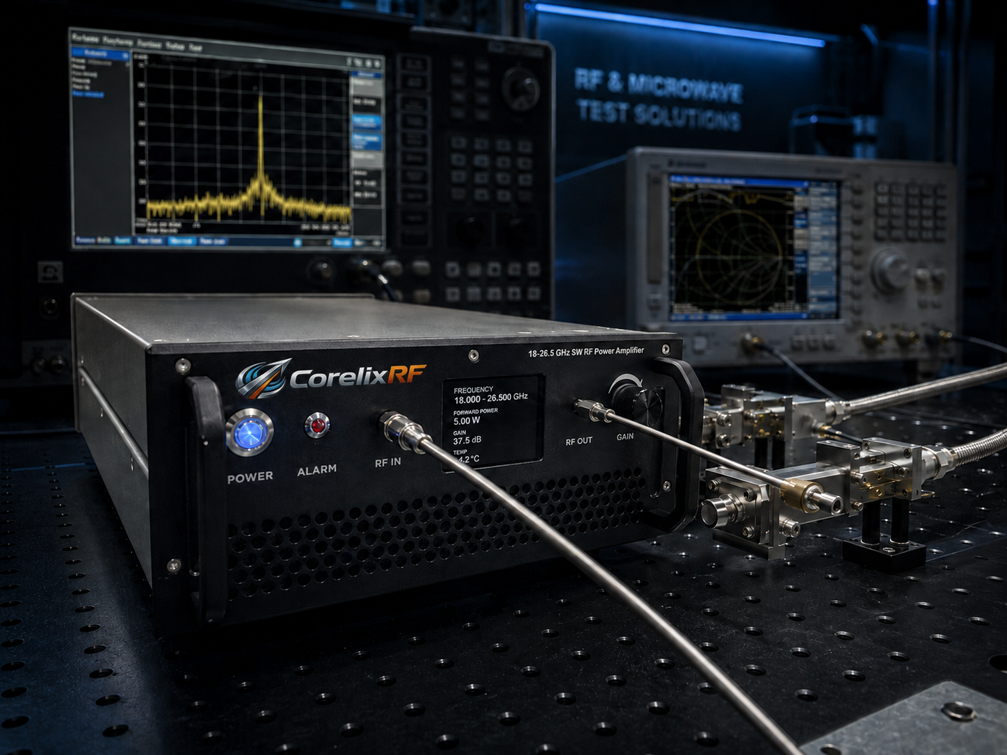
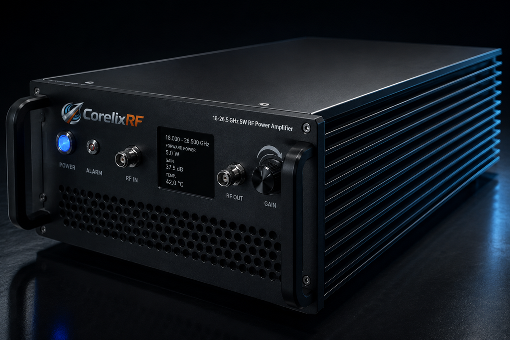
An 18-26.5 GHz 5W K-band RF amplifier is often selected when a microwave bench needs useful output power without the size and facility burden of a larger rack system. The CorelixRF CRF-PA-18000M26500M-5W covers 18 GHz to 26.5 GHz, provides 5 W rated solid-state RF output power, uses GaN SSPA technology, and lists 37 dB minimum small-signal gain. The local datasheet identifies 2.92mm-F RF input and output, an air-cooled small-unit configuration, temperature and current monitoring, alarm protection, and project-ready control interfaces for RF system integration.
This gate review is written for engineers searching for a K-band RF amplifier, 5w rf amplifier, 5w rf power amplifier, or compact GaN SSPA small unit. In this context, a microwave power amplifier is judged by the whole bench, not only by a power number. The review should decide whether the source, adapters, load, cooling, and control method are ready for a repeatable bench record.
Gate 1: Frequency and Reference Plane
The first gate is a frequency plan from 18 GHz to 26.5 GHz. List low, center, high, and application-specific points, then name the exact output reference plane. A small amplifier can still be misapplied if the team compares output at the connector with delivered power after cables, adapters, or fixtures. The test diagram should show source, attenuation, amplifier, output cable, coupler, sensor, and load path.
Gate 2: Source Drive Control
A 37 dB gain stage requires a disciplined source limit. Before RF enable, define maximum source power, startup attenuation, frequency-change behavior, and recovery after a test script fault. If an SDR or swept source controls the bench, software should start from a low-power state and log source level with frequency, current, temperature, and output reading.
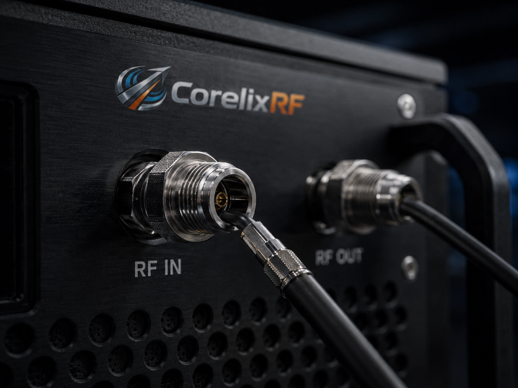
- Confirm 2.92mm-F connector condition before first RF test.
- Record frequency point, drive level, output power, current, and temperature together.
- Keep air inlet and heat-sink clearance visible after cabling.
- Define the operator response to VSWR, current, or temperature alarms.
- Ask for final drawing and control protocol when the bench will be reproduced.
Gate 3: Small Unit Cooling
The source lists air cooling and small-unit packaging. That does not remove thermal responsibility. The bench owner should verify mounting surface, clearance, fan path if used in an enclosure, ambient condition, and service access. A compact RF front-end platform may place the amplifier near sources, filters, switches, or receivers, so thermal behavior should be checked after integration, not only on an open bench.
Gate 4: Protection and Monitoring
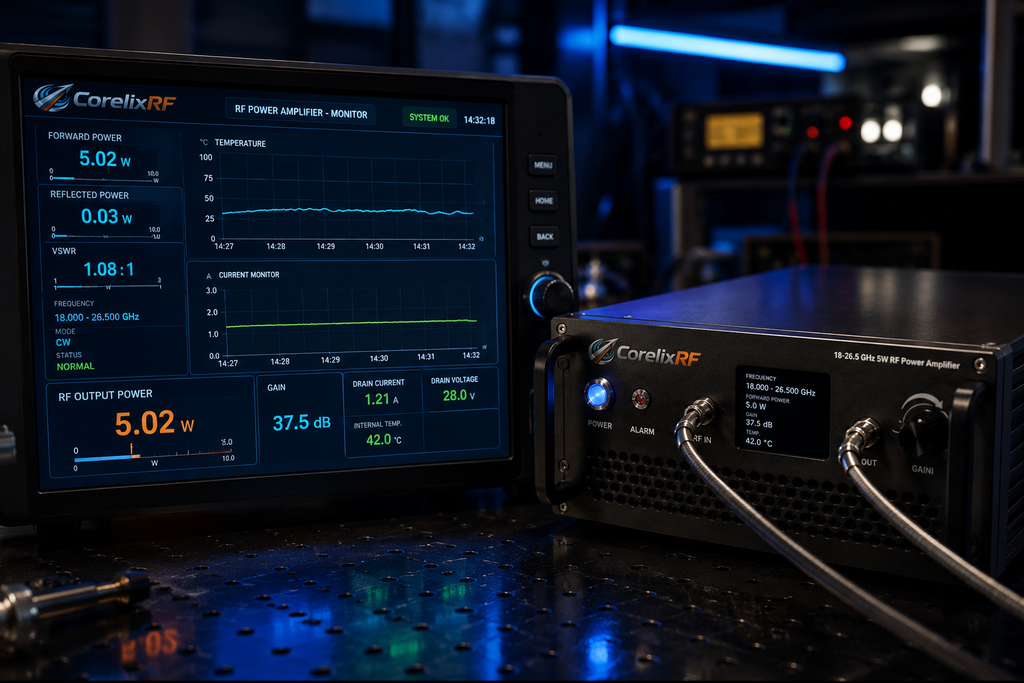
Temperature and current monitoring are useful when the data is tied to the RF condition. The gate review should define what is logged, what alarm states mean, and who can reset the system. Protection should be treated as a boundary for abnormal conditions, not a normal operating method. After a VSWR alarm, inspect the load path before continuing.
Gate 5: Procurement Evidence
The RFQ should include operating band, output target, source type, duty condition, reference plane, connector plan, cooling arrangement, control requirement, and required acceptance records. If a standard small unit needs a different enclosure, monitoring set, or control interface, route the inquiry through custom RF amplifier review. Use the RF amplifier product finder when comparing adjacent K-band and Ka-band choices.
Bench Gate Closeout
Approval is ready when the bench has a fixed reference plane, locked source limit, known load path, documented cooling condition, and defined alarm response. This article stays inside datasheet-supported information and does not claim inventory, certification, or customer deployment. It gives procurement and engineering a practical way to discuss a compact 18-26.5 GHz amplifier without overstating the source material.
The long-tail keyword set is 18-26.5 GHz 5W K-band RF amplifier, 5w rf amplifier, 5w rf power amplifier, GaN SSPA small unit, and microwave power amplifier. These terms fit buyers who are already planning a microwave bench and want integration details, not a generic RF definition.
Receiving Notes for Compact Microwave Labs
A compact microwave lab should keep a receiving note with the amplifier from the first day of use. The note should list the source model, source power limit, external attenuation, cable or adapter set, load type, temperature observation method, and any control connection used during the first successful test. That record is useful when the same 18-26.5 GHz amplifier is later moved to a second bench or used by a different operator.
The note should also separate what is fixed from what is flexible. Frequency range, rated output power, gain, connector type, and cooling format come from the datasheet. Test frequencies, output reference plane, drive level, and enclosure airflow are project choices. Keeping those categories separate prevents procurement from asking for unsupported promises while still giving engineering enough detail to make a decision.
For SEO, this matters because engineers rarely search only for a product name. They search for the problem around the product: K-band output stage, 2.92mm amplifier setup, small unit microwave amplifier, or GaN SSPA bench integration. The article should answer those practical questions without inventing certification, inventory, or field-use claims for the product.
FAQ
What frequency range does CRF-PA-18000M26500M-5W cover?
The local datasheet lists 18 GHz to 26.5 GHz.
What output power and gain are listed?
The source lists 5 W rated RF output power and 37 dB minimum small-signal gain.
What RF connectors are listed?
The datasheet lists 2.92mm-F input and output.
What cooling format is listed?
The source describes an air-cooled small-unit configuration.