
Control Planning Note
The CRF-PA-2350M2550M-100W should be specified as a controlled narrowband subsystem, not as a generic 100 W amplifier. The local datasheet lists 2350 MHz to 2550 MHz operation, 100 W typical saturated RF output power, GaN SSPA architecture, 46 dB minimum and 48 dB typical gain, 20 dB gain adjustment in 0.5 dB steps, SMA-KFD46 input and output, a 160 x 120 x 25 mm compact module configuration, an integrated VCO with 10 Hz frequency step, temperature detection, optional forward/reverse power monitoring, and protection against over-temperature, high VSWR, over-voltage, and over-current conditions.
That specification points toward a narrowband RF power amplifier article with a control-plan angle. The buyer already knows the band. The useful question is how to document frequency selection, gain state, enable timing, source architecture, and acceptance evidence before the amplifier is integrated.
Assumption A: Integrated VCO Behavior Is Part of the Requirement
If the project uses the integrated VCO, the RFQ should define channel list, sweep behavior, step size expectations, dwell time, enable sequence, and how the controller records frequency state. A 10 Hz step capability is only valuable when the system knows how it will command and verify it. If the project instead uses another source architecture, state that clearly so the review does not mix two operating models.
Assumption B: Gain State Must Be Logged
The 20 dB gain-adjustment range in 0.5 dB steps should become a data field in the test record. Record the starting gain state, allowed adjustment range, source condition, measured output, and operator authority. Without that log, a later engineer may reproduce the frequency and still miss the gain condition that created the original result.
Assumption C: The Compact Module Needs a Host Boundary
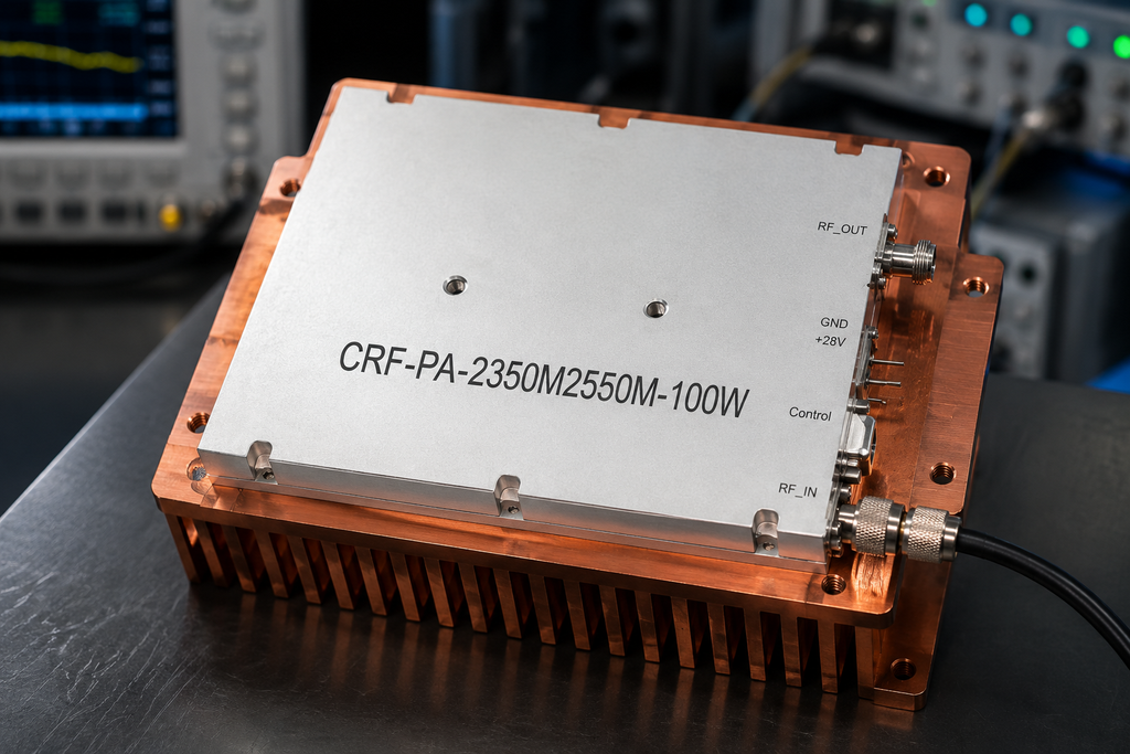
The 160 x 120 x 25 mm module format can help embedded systems, but it does not remove integration work. Define the mounting surface, heat path, DC supply margin, cable route, control connector access, and load. CorelixRF’s RF integration page is the right internal reference because the amplifier is only one part of the controlled RF chain.
Acceptance Table to Request
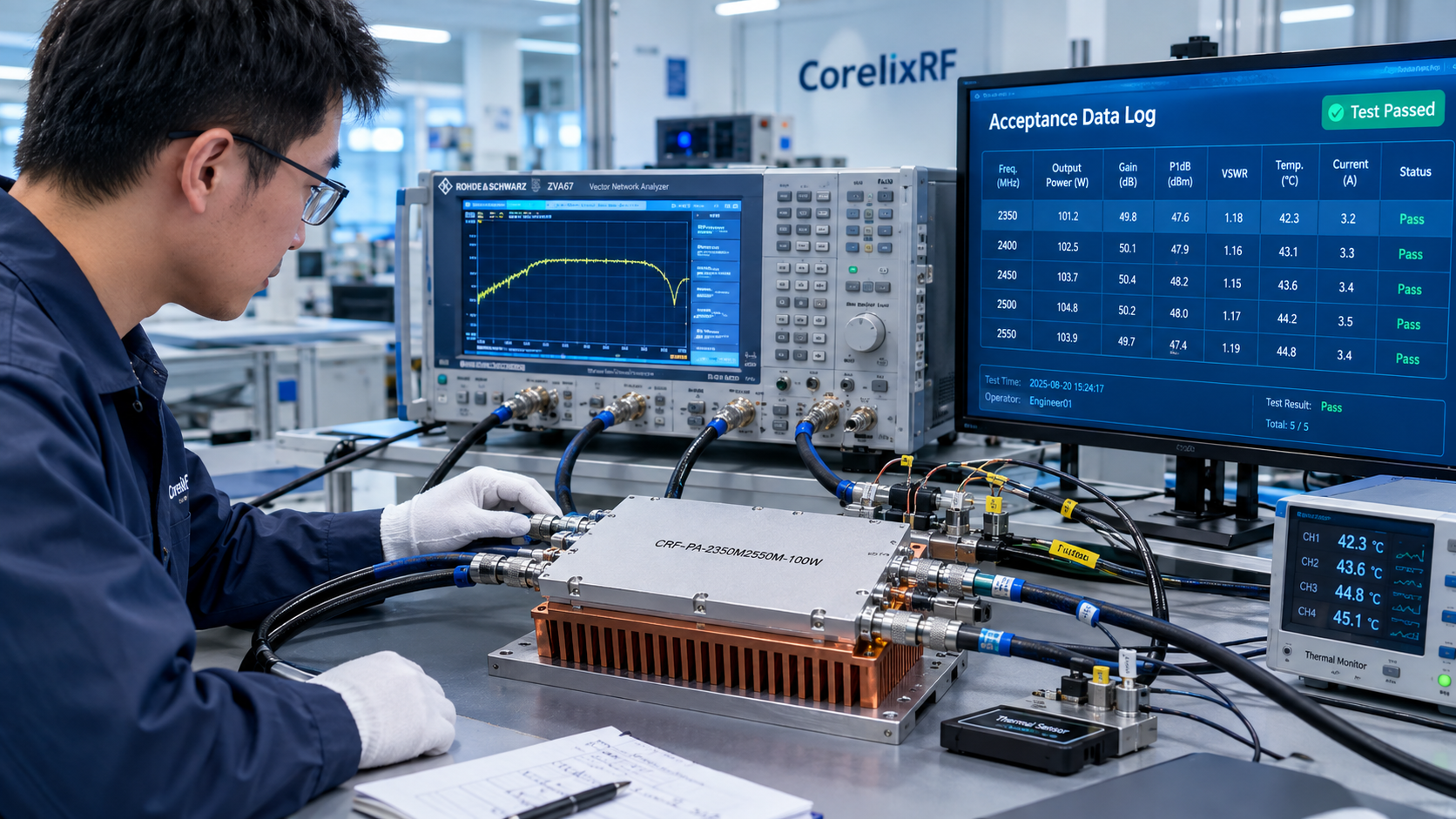
Ask for data at representative points inside 2350 MHz to 2550 MHz, including gain state, output reference plane, thermal condition, control mode, and any monitoring used during the run. If the project depends on frequency-agile operation, request evidence that matches the intended sequence rather than a single fixed-frequency reading. If optional forward or reverse power monitoring is required, identify it explicitly in the RFQ.
Risk Register
The first risk is treating the integrated VCO as a feature without describing how the system will command it. The second risk is accepting output power without recording gain state. The third risk is drawing a compact module into a product before the heat path is proven. The fourth risk is assuming protection behavior without tying it to the host system response.
For comparison across other product families, link readers to the broader RF power amplifier portfolio. For a project-specific frequency window, custom enclosure, monitoring package, or control protocol, the next step is Contact CorelixRF with the control plan attached.
Control Plan Outline
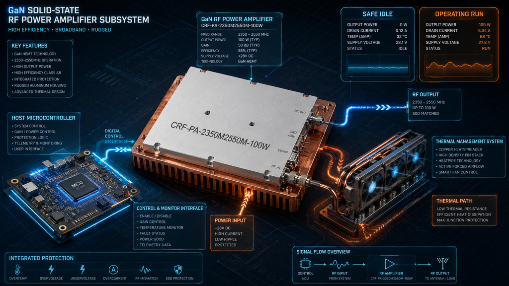
A useful control plan has four states. State one is safe idle: RF disabled, source condition known, frequency command clear, and load connected. State two is low-power verification: frequency command applied, gain set conservatively, and output verified at a safe level. State three is operating run: output, gain state, temperature, and any monitoring signals are logged against each frequency or sweep segment. State four is recovery: source returns to a safe condition, alarm state is recorded, and the operator documents whether the run can be repeated.
Buyer Language to Use
A strong RFQ sentence is concrete: “Review CRF-PA-2350M2550M-100W for a 2350 MHz to 2550 MHz narrowband RF chain using integrated VCO frequency control, defined gain states, a compact module heat path, and frequency-point acceptance data.” That wording is far better than “quote 100 W amplifier” because it tells engineering what behavior must be reviewed. It also gives the SEO article a natural reason to mention narrowband RF power amplifier, integrated VCO, gain adjustment, and project-specific RF subsystem integration without keyword stuffing.
Review Gate
Do not close the planning note until the team can answer three questions: who commands frequency, who owns gain state, and where output power is measured. If those answers are missing, the amplifier may still be a strong candidate, but the RFQ is not ready.
FAQ
What frequency range is listed for CRF-PA-2350M2550M-100W?
The local CorelixRF specification evidence lists 2350 MHz to 2550 MHz.
What output power is listed?
The local datasheet lists 100 W typical saturated output. The usable condition should still be reviewed against waveform, reference plane, load, thermal boundary, and acceptance method.
What should be included in the RFQ?
Include frequency points, waveform, source level, output reference plane, load condition, connector path, cooling boundary, control interface, alarm behavior, and requested test data.
Does this article claim stock, certification, or customer deployment?
No. It stays inside local product specifications and general engineering guidance.
What is the main integration caution?
Do not separate the RF power requirement from VCO command behavior, gain state, and thermal mounting.