
Before You Power the Module
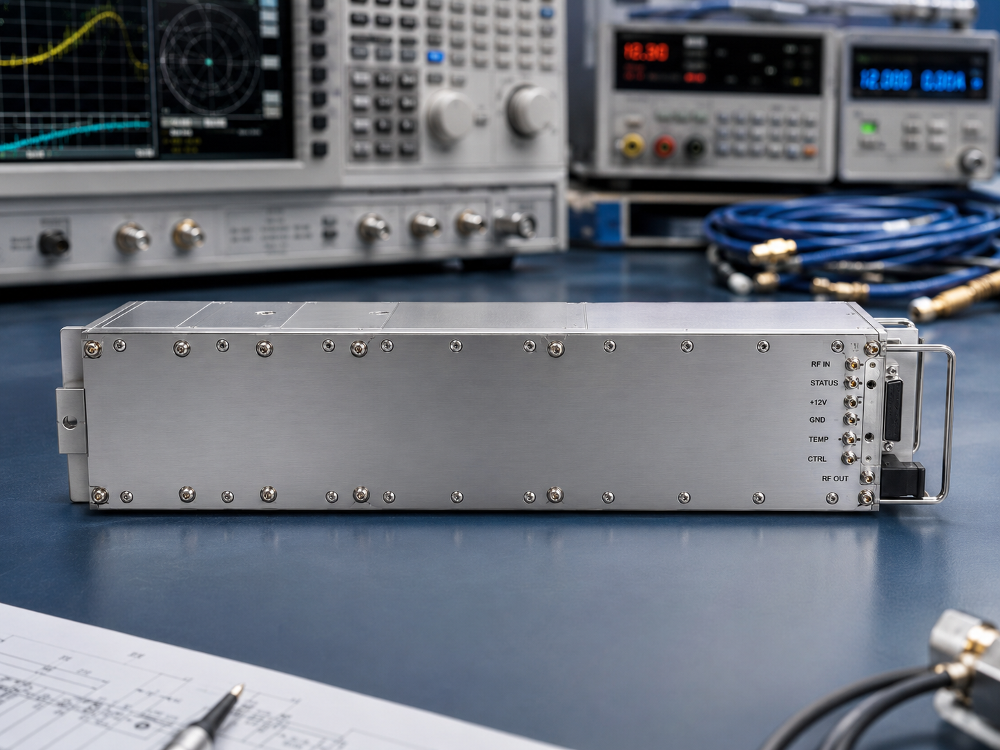
This article is a commissioning checklist, not a buying guide. The CRF-PA-4K400M-100W-M is listed locally as an LDMOS SSPA covering 4 kHz to 400 MHz with 100 W rated output power, 50 dB minimum small-signal gain, SMA-Female input, N-Female output, a 329.5 x 104.8 x 61 mm module configuration, temperature and current monitoring, alarm protection, and project-ready control interfaces. That makes the module relevant to low-frequency RF test work, conducted immunity-style setups, communication validation, and project-specific integration when the heat path and RF path are properly defined.
Use this checklist when a low-frequency EMC RF amplifier has to move from datasheet review into a real assembly. The format is deliberately operational: each item should be checked, assigned, or marked not applicable before the RFQ becomes a purchase decision.
1. Define the Frequency Job
Record the exact low, mid, and high frequencies inside 4 kHz to 400 MHz. If the project involves swept operation, include step size, dwell time, leveling method, and the maximum source condition. If it uses fixed channels, list those channels and their acceptance limits. Do not let “4 kHz to 400 MHz” do all the work; that range is a product boundary, not a test method.
2. Freeze the Mounting and Heat Path
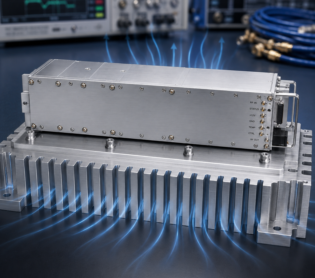
The listed module size is only the beginning of the mechanical design. The integrator should define the mounting surface, heat sinking, airflow if used, nearby heat sources, service access, cable bend space, and how temperature readings will be observed. A module can be physically compact and still fail the system review if heat has nowhere reliable to go.
3. Lock the Connector and Load Plan
The SMA-Female input and N-Female output should appear in the cable list and fixture drawing. A RF power amplifier used at low frequencies may connect to larger loads, injection fixtures, couplers, or long cable paths. Record the load rating and mismatch assumption before applying drive. If the final equipment needs a different connector or output path, request that review before mechanical release.
4. Write the Source-Limit Rule
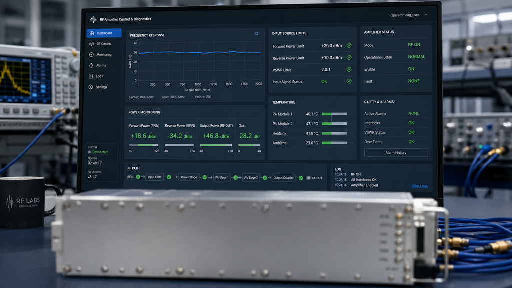
With 50 dB minimum gain, source drive deserves a written limit. The commissioning checklist should state the starting source level, the allowed adjustment path, the measurement instrument range, and the person authorized to enable RF. This is not red tape. It prevents a low-frequency amplifier from being treated like a passive rack accessory.
5. Verify Monitoring and Alarm Behavior
The local data references diagnostics and alarm protection. The system procedure should explain how those signals are used: what is logged, what causes a stop, who can reset the chain, and how the source returns to a safe state. CorelixRF’s RF integration guidance is useful here because the amplifier, control interface, and operator method are one system.
6. Build the Acceptance Packet
The packet should include frequency-point data, source level, measured output, gain notes, thermal observations, connector confirmation, load identity, alarm response, and any deviation from the planned setup. If the amplifier will be embedded in customer equipment, include the enclosure drawing and heat path. If the work is mainly bench validation, include the bench topology and operator instructions.
Completion Rule
The CRF-PA-4K400M-100W-M is ready for quotation review when every checklist item has an owner. If the team cannot answer one item, send that uncertainty through Contact CorelixRF instead of filling the gap with an assumption. That is the clean way to specify a low-frequency RF amplifier without overstating what the datasheet proves.
Commissioning Record Template
Use a short commissioning record for every meaningful run. Include date, operator, source model, amplifier model, frequency or sweep plan, starting source level, final source level, measured output, load identity, cable set, fixture identity, mounting condition, thermal note, alarm state, and deviation note. The point is not paperwork for its own sake. The point is that low-frequency setups often evolve through small fixture and cable changes, and those changes can make two readings incomparable.
Stop Conditions
Stop the run if the load is not confirmed, the source limit is unknown, the heat path is not ready, a connector has been changed without updating the record, or an alarm appears without a written response procedure. Restart only after the setup is back in a known condition. This keeps the module checklist practical for engineering benches, pre-compliance work, and system integration where multiple teams may share the same RF hardware.
FAQ
What frequency range is listed for CRF-PA-4K400M-100W-M?
The local CorelixRF specification evidence lists 4 kHz to 400 MHz.
What output power is listed?
The local datasheet lists 100 W. The usable condition should still be reviewed against waveform, reference plane, load, thermal boundary, and acceptance method.
What should be included in the RFQ?
Include frequency points, waveform, source level, output reference plane, load condition, connector path, cooling boundary, control interface, alarm behavior, and requested test data.
Does this article claim stock, certification, or customer deployment?
No. It stays inside local product specifications and general engineering guidance.
What is the main integration caution?
The module needs a defined heat path, source limit, and controlled load before RF drive is enabled.