
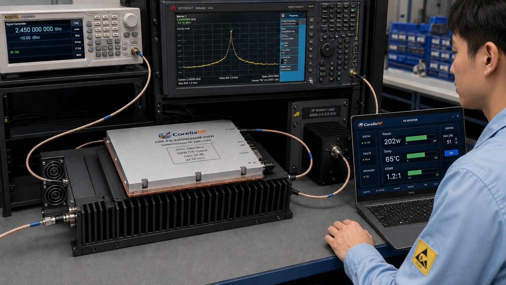
A 2400-2500 MHz 200W narrowband RF amplifier is a strong fit when the project already knows its operating window and does not need a broad multi-band power amplifier. The CorelixRF CRF-PA-2400M2500M-200W datasheet describes a GaN solid-state narrowband amplifier for 2400 MHz to 2500 MHz with 200 W rated CW output power, gain listed at 49 dB minimum, 51 dB typical, and 53 dB maximum, gain adjustment, 24-32 V operating voltage, SMA-KFD46 RF connectors, D-Sub 15-pin control and power connector, compact 200 x 158 x 25 mm mechanical size, and external heat-sink cooling. For buyers evaluating narrowband RF amplifier options, this is a focused integration case.
Why Choose Narrowband Instead of Wideband
A wideband amplifier is attractive when one platform must cover many bands. A narrowband amplifier is often better when the system must concentrate power, thermal design, gain behavior, and mechanical integration around a known frequency window. In this case, 2400-2500 MHz is a defined 100 MHz band, so the RFQ can focus on output power, heat sinking, control interface, frequency-source options, and load condition instead of paying for unnecessary coverage.
CorelixRF lists UHF and specialized amplifier routing for lower-frequency and focused-band projects, while the product navigation also includes broader RF power amplifier pages. In content terms, the article should guide readers toward the closest platform and then the contact form when they need exact model confirmation.
Datasheet Details That Matter
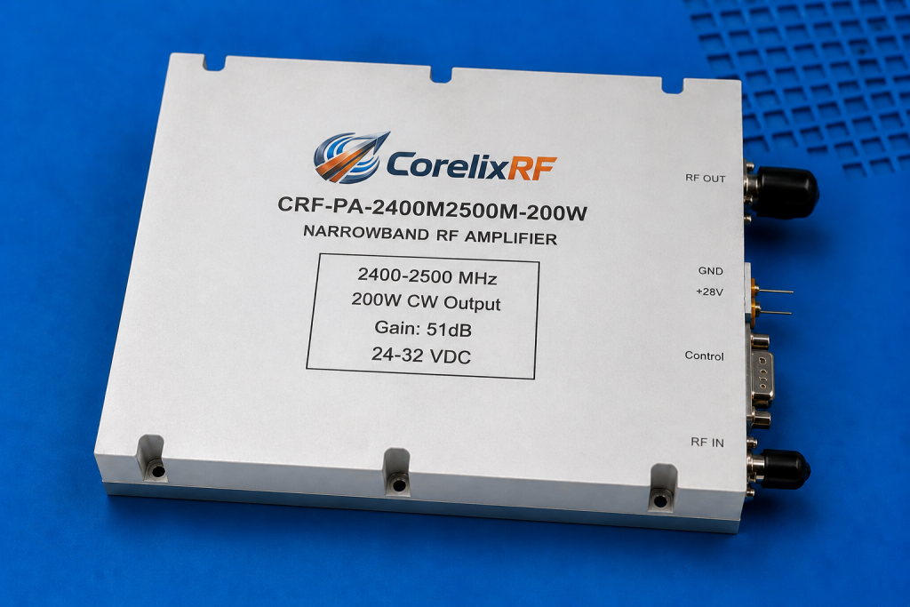
The local datasheet lists 2400-2500 MHz frequency range, 160 W minimum and 200 W typical Psat, 49/51/53 dB gain values, 20 dB gain adjustment range with 0.5 dB step, 20 dB maximum noise figure for the M version, 1.5 maximum input VSWR for the M version, -60 dBc spurious, -10 dBc harmonics, and 24/28/32 V operating voltage range with 30 A typical and 36 A maximum current.
It also lists PA enable/disable time under 100 microseconds, SMA-KFD46 RF connectors, D-Sub 15-pin female control/power connection, approximately 1.4 kg mass, external heat-sink cooling, optional RS485 monitoring and control, forward and reverse power indication, gain control, temperature monitoring, current monitoring, over-temperature protection, over-VSWR protection, over-voltage protection, and over-current protection.
M Version and V Version Review
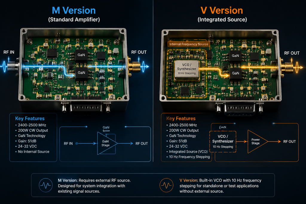
The datasheet notes available M and V configurations. The M version is described without an internal VCO, while the V version includes an internal VCO source with 10 Hz stepping and frequency or bandwidth adjustment references. That distinction is important. If the system already has an RF source, the M version may be the right discussion. If the project needs source integration, the V version should be reviewed with the signal architecture.
Thermal Planning for Compact Modules
The 200 x 158 x 25 mm size makes the amplifier attractive for compact integration, but it does not remove the need for thermal engineering. The datasheet specifies external heat-sink cooling. The buyer should provide expected duty condition, enclosure temperature, mounting surface, airflow, and heat-sink plan before assuming full-power operation is practical.
Where This Amplifier Fits
The listed applications include narrowband RF system amplification, communication systems, RF test and measurement systems, and project-specific RF source integration. That makes the model relevant to fixed-band RF links, production test fixtures, controlled RF stimulus paths, and integrated source-plus-amplifier assemblies. It should not be presented as a universal 2.4 GHz solution without reviewing load match, regulatory context, duty mode, and enclosure limits.
Use natural internal links to route readers to narrowband amplifier options, RF testing and validation guidance, and the CorelixRF contact page for a model-specific review.
RFQ Inputs to Send
Provide the exact 2400-2500 MHz operating need, target output power, input source level, whether an internal VCO is required, gain-control expectations, available DC supply, control preference, duty condition, thermal mounting plan, connector constraints, and documentation needs. If the mechanical envelope or control connector must change, state that early as a custom RF amplifier requirement.
For procurement review, the safest next step is to share the operating frequency, target output power, waveform, duty cycle if pulsed, available cooling, RF connector preference, control interface, load condition, and documentation requirement before requesting a final quotation. That keeps the discussion tied to measured data and integration constraints rather than a generic catalog match.
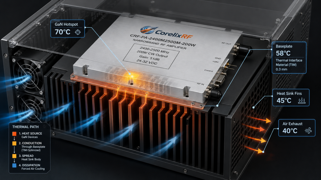
Because this is a compact narrowband module, the final WordPress draft should avoid treating size as a substitute for thermal readiness. A small outline is useful only when the mounting surface, heat-sink mass, airflow, duty profile, and control wiring are planned together. This makes the article more valuable to design engineers and purchasing teams: it frames the amplifier as an integration component that needs a disciplined RFQ, not as a drop-in part for every 2.4 GHz system.
FAQ
Is this a broadband amplifier?
No. The datasheet describes a narrowband 2400-2500 MHz amplifier.
What output power is listed?
The datasheet lists 200 W typical CW output power, with 160 W minimum Psat shown in the electrical table.
Does it support gain adjustment?
Yes. The local datasheet lists a 20 dB gain adjustment range with 0.5 dB step.
What cooling is required?
The datasheet lists external heat-sink cooling, so the system thermal path must be reviewed.
What is the difference between M and V versions?
The M version is described without internal VCO, while the V version includes internal VCO source functionality. Final choice should be confirmed by project architecture.
CTA: Contact CorelixRF