
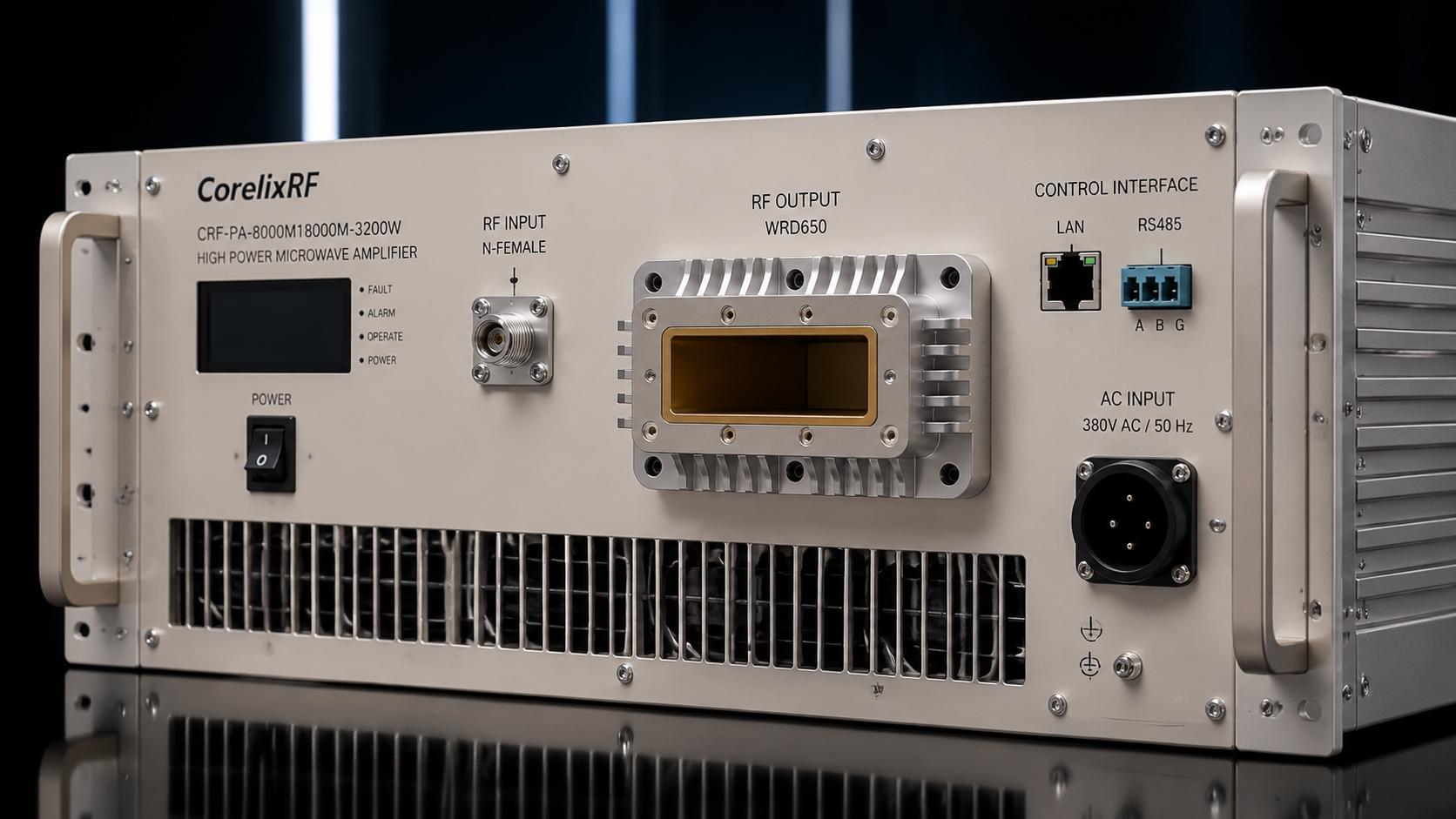
An 8-18 GHz 3200W high-power microwave amplifier is a system-level RF asset, not a simple catalog component. The CorelixRF CRF-PA-8000M18000M-3200W datasheet describes a GaN SSPA covering 8,000 MHz to 18,000 MHz with 3200 W output power, 63 dB minimum gain, 20 dB gain control, N-Female input, WRD650 waveguide output, RS485/LAN control, AC 380 V supply, and air cooling. For engineers searching for a 6-18 GHz microwave amplifier or wider X/Ku-band power platform, this specification is a useful high-power reference.
The Selection Problem at 8-18 GHz
Wideband microwave amplification across 8-18 GHz is difficult because output power, gain flatness, harmonic behavior, spurious performance, connector choice, and thermal design all interact. At 3200 W, the review becomes even more constrained. The output path must support high RF power across a broad band, and the waveguide interface must be coordinated with the test fixture, load, coupler, or antenna system.
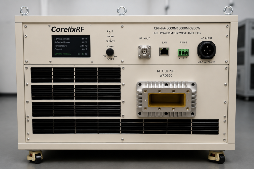
This is why the first RFQ should not ask only for “price and lead time.” A technical buyer should define the operating band, required output level, acceptable gain ripple, continuous-wave or waveform condition, drive level, cooling method, control method, shutdown logic, and documentation package. The CorelixRF high frequency RF amplifier content emphasizes measured data and engineering review, which is the right framing for this power class.
Datasheet-Backed Technical Snapshot
The local datasheet lists 8,000-18,000 MHz frequency range, 3200 W output power, 63 dB minimum small-signal gain, -6 to +6 dB gain flatness, gain control up to 20 dB, 0 dBm maximum input, harmonics from -15 to -8 dBc, -15 dBm/MHz noise floor, and -60 dBc spurious. It identifies 50 ohm input impedance with 1.5:1 typical VSWR, N-Female input, WRD650 waveguide output, RS485/LAN control, AC 380 V plus or minus 10 percent power, 0 to +50 degrees C operating temperature, and air cooling.
Those numbers give enough information to start an engineering review, but final purchase approval should still rely on measured curves for the exact build. In a high-power solid state RF power amplifier, the tested response across the band is more useful than a single rated-power value.
Why WRD650 Output Matters
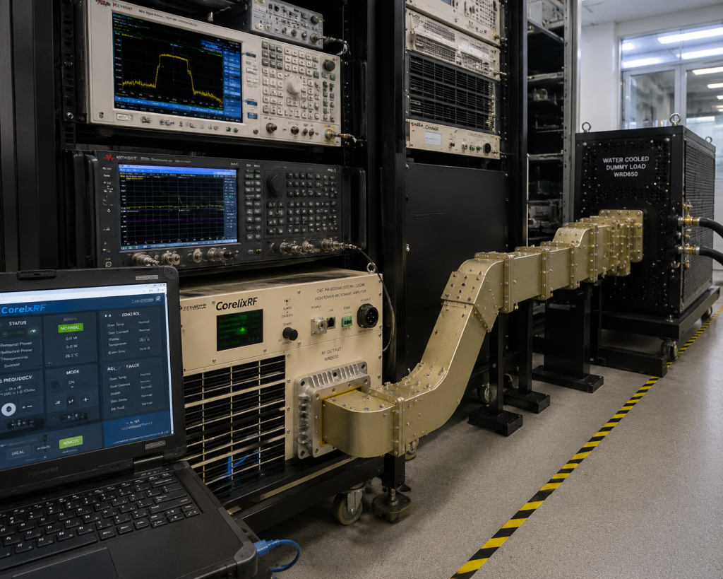
The WRD650 output indicates that the downstream RF path must be planned as a waveguide system. Engineers should review transitions, directional couplers, loads, antenna feeds, calibration points, and physical clearances. If the amplifier is installed in a rack or shelter, waveguide routing can become a mechanical constraint just as important as the RF specification.
Monitoring and Remote Operation
The datasheet references real-time temperature monitoring, current monitoring, optional forward and reverse power monitoring, and LAN remote monitoring. Those functions are especially relevant when the amplifier is used in automated RF testing, system-level interference evaluation, or production validation. Request the interface control document so software teams can monitor state, alarms, and operating limits.
Application Fit
The datasheet lists test and measurement instrumentation, communication systems, RF interference or EW system-level testing, and aerospace control systems. These are credible application directions, but each requires a different acceptance checklist. A communication test platform may prioritize spectral quality and gain repeatability. A system-level interference test may emphasize power margin and load tolerance. An aerospace-control environment may require deeper review of interface, monitoring, enclosure, and operating procedures.
RFQ Checklist
Before contacting CorelixRF, document the required band within 8-18 GHz, target power at the output or load, duty condition, input drive, allowable gain flatness, load VSWR conditions, expected operating time, AC power availability, cooling path, WRD650 interface plan, rack or cabinet limitations, remote control needs, and required measured data. Use the RF testing and validation page as the internal link for documentation-focused readers and the contact page for direct engineering submission.
Avoiding Over-Specification
A 3200 W amplifier may be unnecessary if the real system needs lower power over a narrower band. If the application only needs part of the band, CorelixRF may be able to review a narrower or lower-power path. Conversely, if the project requires additional filtering, enclosure changes, different control logic, or a non-standard waveguide layout, it should be framed as a custom RF amplifier project.
For procurement review, the safest next step is to share the operating frequency, target output power, waveform, duty cycle if pulsed, available cooling, RF connector preference, control interface, load condition, and documentation requirement before requesting a final quotation. That keeps the discussion tied to measured data and integration constraints rather than a generic catalog match.
The article should be reviewed as a technical buying guide rather than a product announcement. That keeps it aligned with engineers who are comparing RF power, gain, waveguide interface, cooling, control, and measured performance evidence. It also avoids overreaching into claims about fielded systems or customer outcomes. The useful promise is process clarity: CorelixRF can review the specification against the buyer’s operating band, integration limits, and test documentation needs.
FAQ
What frequency range does this model cover?
The local datasheet lists 8,000 MHz to 18,000 MHz.
What rated output power is listed?
The datasheet lists 3200 W output power.
Which interfaces are listed?
RF interfaces are N-Female input and WRD650 waveguide output; control is listed as RS485/LAN.
What cooling method is listed?
The datasheet lists air cooling.
What data should buyers request?
Ask for output power, gain, gain flatness, harmonics, spurious, noise floor, thermal behavior, protection behavior, and control protocol details for the exact configuration.