
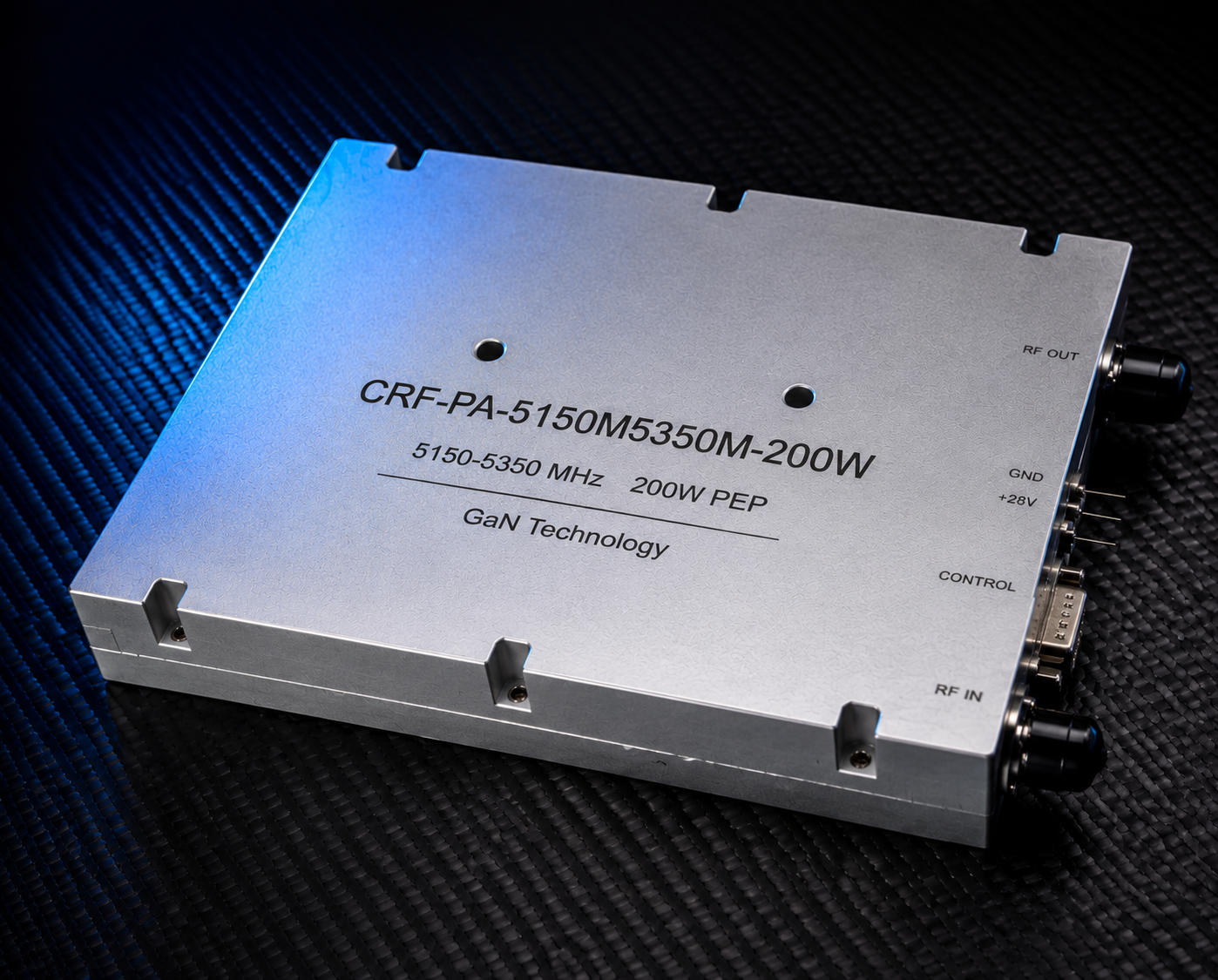
A 5150-5350 MHz 200W narrowband RF amplifier is selected when the operating band is already defined and the project needs concentrated RF output instead of broad multi-band coverage. The CorelixRF CRF-PA-5150M5350M-200W datasheet describes a third-generation GaN solid-state RF power amplifier covering 5150 MHz to 5350 MHz with 200 W rated CW output power, 49 dB minimum gain, 51 dB typical gain, 53 dB maximum gain, 20 dB gain adjustment in 0.5 dB steps, SMA-KFD46 RF connectors, a D-Sub 15-pin control/power connector, 24-32 V operating voltage, and external heat-sink cooling. For buyers reviewing narrowband RF amplifier options, this model provides a focused fixed-band reference.
Why a Narrowband 5150-5350 MHz Amplifier Makes Sense
A narrowband amplifier can be the better choice when the system does not need a wide 2-6 GHz or 6-18 GHz platform. By concentrating the design around 5150-5350 MHz, the procurement discussion can focus on output power, gain adjustment, source architecture, DC supply, thermal path, monitoring, and protection behavior. That helps engineering and purchasing teams avoid comparing products that solve different problems.
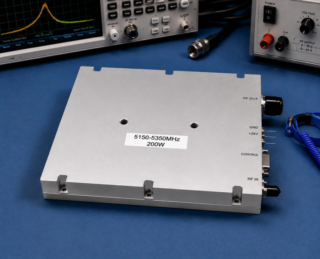
The local specification lists primary applications such as narrowband RF system amplification, communication systems, RF test and measurement systems, and project-specific RF source integration. These categories are broad, so the article should guide readers toward a project review instead of implying that every 5 GHz system has identical requirements.
Datasheet Parameters That Should Drive the RFQ
The datasheet lists 5150-5350 MHz frequency range, 160 W minimum and 200 W typical Psat, 49/51/53 dB gain values, 20 dB gain adjustment range, 0.5 dB gain adjustment step, 20 dB maximum noise figure for the M version, 1.5 maximum input VSWR for the M version, -60 dBc spurious, -10 dBc second and third harmonics, 24 V minimum, 28 V nominal, and 32 V maximum operating voltage, 30 A typical and 36 A maximum operating current, and PA enable/disable time under 100 microseconds.
It also lists SMA-KFD46 RF connectors, D-Sub 15-pin female control and power connector, approximately 200 x 158 x 25 mm mechanical dimensions, 1.4 kg mass, external heat-sink cooling, optional RS485 monitoring/control, forward and reverse power indicators, temperature analog output, gain control, and alarm reset options where applicable.
M Version and V Version Options
The specification notes M and V configurations. The M version is described without an internal VCO, while the V version includes an internal VCO source with 10 Hz stepping and frequency or bandwidth adjustment references. That distinction is important for system architecture. If the buyer already has a signal source, the M version may be the right starting point. If the system needs source integration, the V version should be reviewed with frequency-control, bandwidth, and software requirements.
Thermal Design Is Part of the Product Review
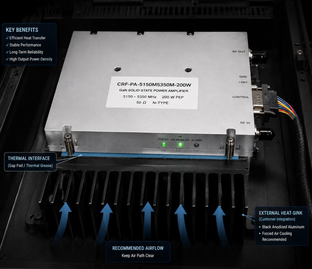
The compact 200 x 158 x 25 mm format is attractive for integrated systems, but the datasheet clearly points to external heat-sink cooling. The buyer should provide heat-sink size, mounting surface, airflow, enclosure temperature, duty condition, and expected operating time. A compact RF power amplifier can only perform correctly when the mechanical and thermal path is designed with the RF requirement.
Protection and Monitoring Checklist
The datasheet references over-temperature shutdown and recovery, over-VSWR locked shutdown, over-voltage lock above 32 V, and over-current lock above 38 A. These are useful details for integrators because they affect firmware, operator procedure, and recovery behavior after a fault. For automated test systems, optional RS485 monitoring/control, forward/reverse power indication, temperature output, and alarm reset behavior should be reviewed before the control software is finalized.
Internal Routing for Readers
A reader comparing narrow fixed-band products should start with the narrowband amplifier family page. A reader who is still deciding between narrowband and broadband coverage can also review the broader RF amplifier category. For documentation and acceptance planning, the RF testing and validation page is a natural supporting link. Final requirements should go through the CorelixRF contact page so engineering can confirm configuration, test data, and integration constraints.
RFQ Inputs for 5150-5350 MHz Projects
Send the exact frequency range, desired output power, input-source plan, whether the VCO option is needed, expected input drive, duty condition, DC supply availability, heat-sink plan, enclosure temperature, control interface, connector requirements, load condition, and documentation needs. If the project needs a different mechanical shape, connector arrangement, monitoring mode, or source-control behavior, describe it as a custom RF amplifier requirement from the start.
For SEO and sales review, keep the claims limited to the source datasheet. Do not add certification, stock, lead-time, customer-case, or regulatory claims unless CorelixRF provides separate public evidence. The useful conversion message is that the datasheet defines a fixed-band GaN SSPA platform and that buyers can request a project-specific amplifier review.
FAQ
What frequency range does the CRF-PA-5150M5350M-200W cover?
The local datasheet lists 5150 MHz to 5350 MHz.
What output power is listed?
The datasheet lists 200 W typical CW output power, with 160 W minimum Psat shown in the electrical table.
Does the model support gain adjustment?
Yes. The datasheet lists a 20 dB gain adjustment range with 0.5 dB step.
What cooling is required?
The specification lists external heat-sink cooling, so the thermal path must be designed into the system.
What is the difference between M and V versions?
The M version is described without internal VCO, while the V version includes internal VCO source functionality with 10 Hz stepping. The right option depends on the source architecture.