
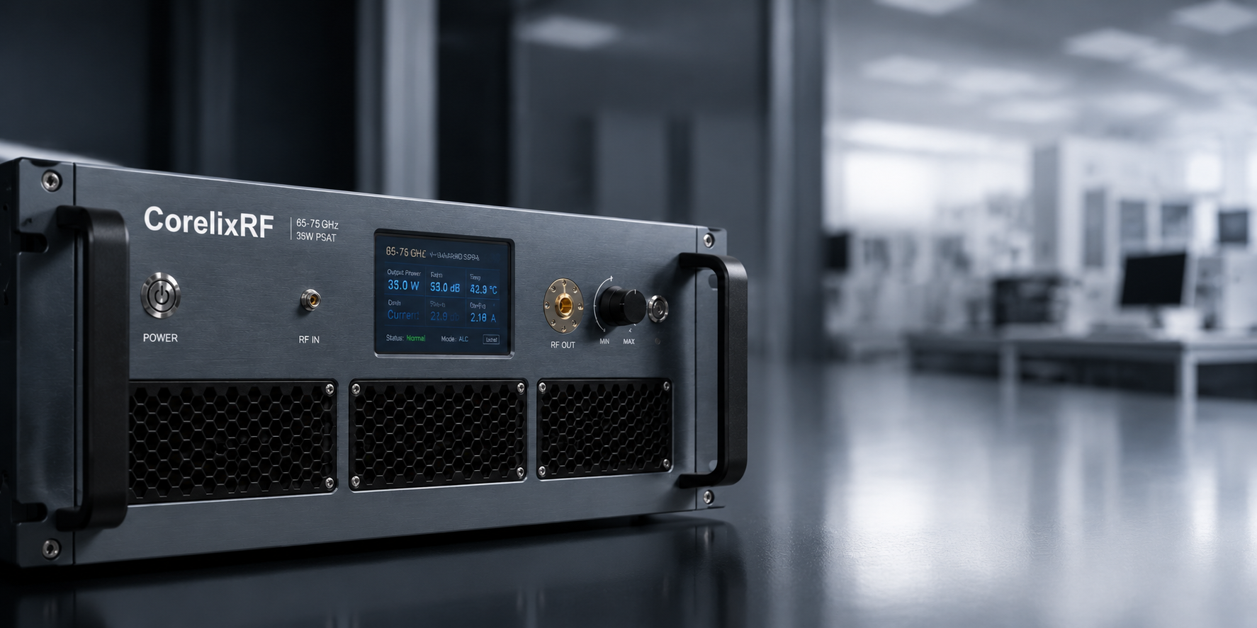
A 65-75 GHz 35W mmWave power amplifier is selected when a project needs meaningful RF power in a V-band window where waveguide interfaces, gain flatness, thermal control, and measured data are central to success. The CorelixRF CRF-PA-65000M75000M-35W datasheet describes a GaN SSPA covering 65 GHz to 75 GHz with 35 W output power, 56 dB minimum gain, 15 dB gain control, WR15 input and output, RS485/LAN control, AC 220 V supply, forced-air cooling, and 19-inch 4U mechanical format. For engineers comparing millimeter-wave amplifier options, those are the first facts to confirm.
Why V-Band Amplifier Selection Is Different
At 65-75 GHz, a power amplifier cannot be evaluated like a low-frequency module. The RF path is strongly affected by waveguide alignment, transition quality, fixture repeatability, calibration method, thermal rise, and test instrumentation limits. A small mismatch or mechanical change can alter measured power and stability. That makes documentation and application review especially important.
CorelixRF presents high frequency RF amplifier support as a datasheet-based and engineering-review process. That is appropriate for V-band projects because the buyer usually needs more than a rated-power line. They need to know the amplifier interface, gain behavior, protection functions, control method, and what measured data can be supplied for technical approval.
Datasheet Parameters for the 65-75 GHz 35W Model
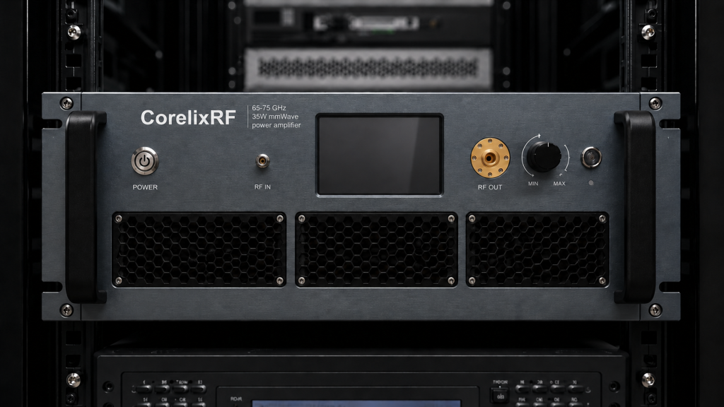
The local specification lists 65-75 GHz frequency range, 35 W output power, 56 dB minimum small-signal gain, -10 to +10 dB gain flatness, up to 15 dB gain control, 50 ohm input impedance with 1.5:1 typical VSWR, -20 dBc harmonics, -60 dBc spurious, WR15 front-panel input and output, RS485 and LAN control, AC 220 V plus or minus 10 percent at 50/60 Hz, 19-inch 4U structure, 0 to +50 degrees C operating temperature, and forced-air cooling.
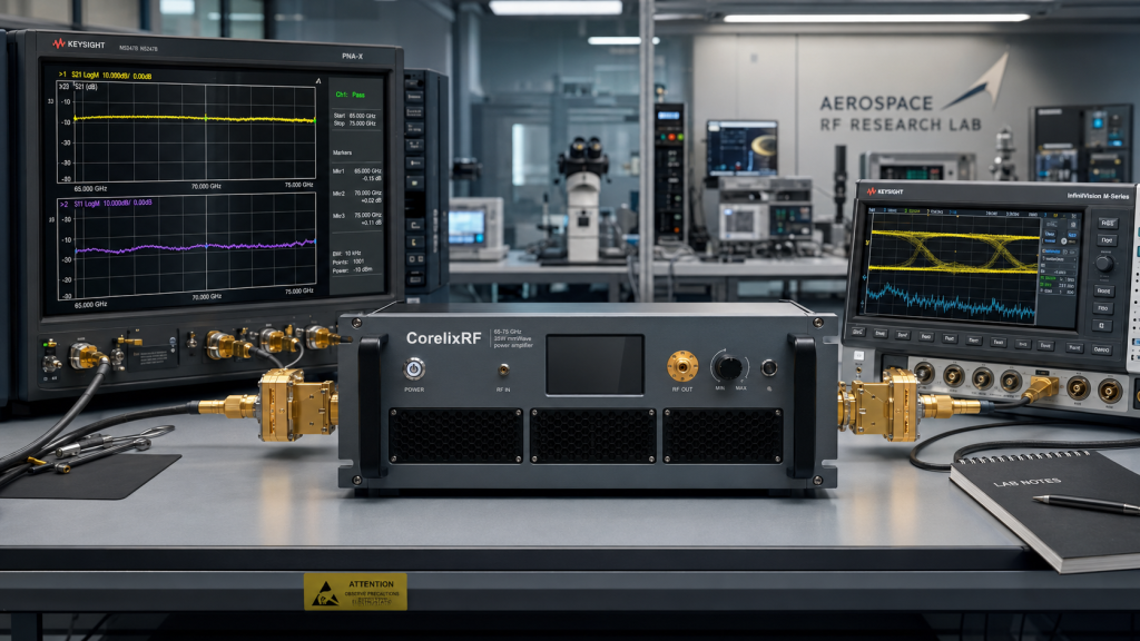
Those parameters support early selection, but final approval should be based on measured output power, gain flatness, spectrum, thermal, and protection behavior for the actual unit or project configuration. For a solid state RF power amplifier at V-band, the measurement setup should be part of the procurement discussion.
WR15 Interface Planning
WR15 input and output are a defining integration detail. Engineers should plan waveguide routing, flange access, calibration transitions, directional couplers, loads, antenna feed, and safe handling before finalizing the rack layout. If the amplifier must connect to an existing system, provide drawings or interface constraints in the RFQ.
Monitoring and Protection
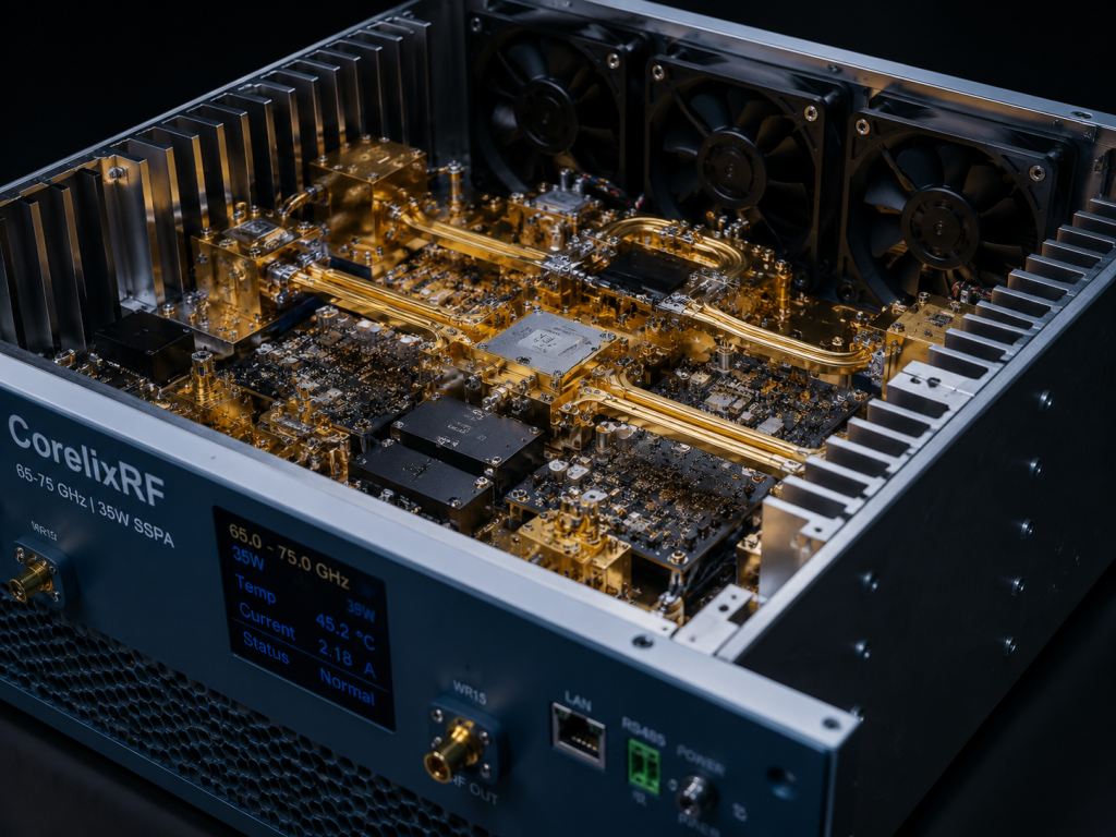
The datasheet lists real-time temperature monitoring, real-time current monitoring, optional forward and reverse power monitoring, and built-in alarm/fault protection. It also references over-temperature and other protection behavior in the protection section. In a high-frequency test platform, these functions help operators identify unsafe conditions before they damage expensive downstream hardware.
Application Directions
The datasheet lists test and measurement instrumentation, communication systems, RF interference system-level testing, and aerospace control systems. These are broad technical categories, so the article should explain how buyers narrow the application. A lab may need repeatable swept-frequency data. A communication integration team may focus on gain stability and spectral behavior. A system-level test group may care more about remote control, fault reporting, and fixture compatibility.
Readers can be routed naturally to the millimeter-wave amplifier page, the RF testing and validation resource, and the CorelixRF contact page for final project review.
RFQ Checklist for 65-75 GHz Projects
Send the exact frequency window, target output power, whether the test is CW or waveform-based, expected input drive, measurement setup, WR15 connection plan, waveguide length and transitions, load or antenna condition, operating time, lab ambient conditions, AC power availability, rack constraints, and required documentation. If the design needs different mechanical packaging, connector access, control logic, or environmental assumptions, frame it as a custom RF amplifier request.
Avoid Claims That Need Project Evidence
For SEO content, do not claim certification, inventory, customer deployment, or guaranteed performance unless it is supported by a public page or a project document. The safer message is that the CRF-PA-65000M75000M-35W datasheet provides a V-band GaN SSPA reference and that final measured data should be requested for project review.
For procurement review, the safest next step is to share the operating frequency, target output power, waveform, duty cycle if pulsed, available cooling, RF connector preference, control interface, load condition, and documentation requirement before requesting a final quotation. That keeps the discussion tied to measured data and integration constraints rather than a generic catalog match.
For search intent, the V-band angle should stay precise. Readers looking for a 65-75 GHz 35W mmWave power amplifier are usually past general education and are comparing practical integration risks. The copy should therefore emphasize WR15 interface planning, measured data requests, thermal and control review, and safe RFQ preparation. That approach is more credible than broad marketing language and better aligned with engineers who need a defensible supplier conversation.
FAQ
What frequency range does the model cover?
The local datasheet lists 65 GHz to 75 GHz.
What output power is listed?
The datasheet lists 35 W output power.
What RF connectors are listed?
The datasheet lists WR15 input and output on the front panel.
What control interfaces are listed?
The datasheet lists RS485 and LAN control.
What should be checked before ordering?
Check waveguide interface, measured RF data, thermal behavior, control protocol, protection behavior, and rack integration constraints.