
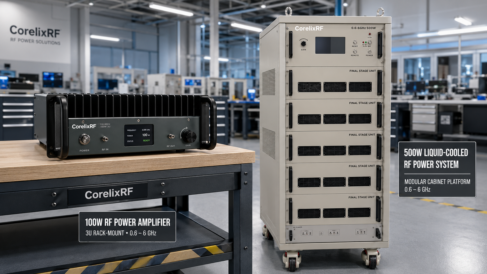
A 600 MHz to 6 GHz EMC amplifier is usually selected after the engineer understands the test objective, not only after reading an output-power line. The amplifier must cover the required band, deliver enough RF power at the load or antenna path, survive mismatch events, and provide an interface that fits the automation environment. CorelixRF local datasheets for the CRF-PA-600M6000M series show two useful reference points: a 100 W GaN SSPA in a 3U rack-mount format and a 500 W GaN SSPA in a cabinet format. Both cover 600 to 6,000 MHz, but they are not interchangeable in the system design.
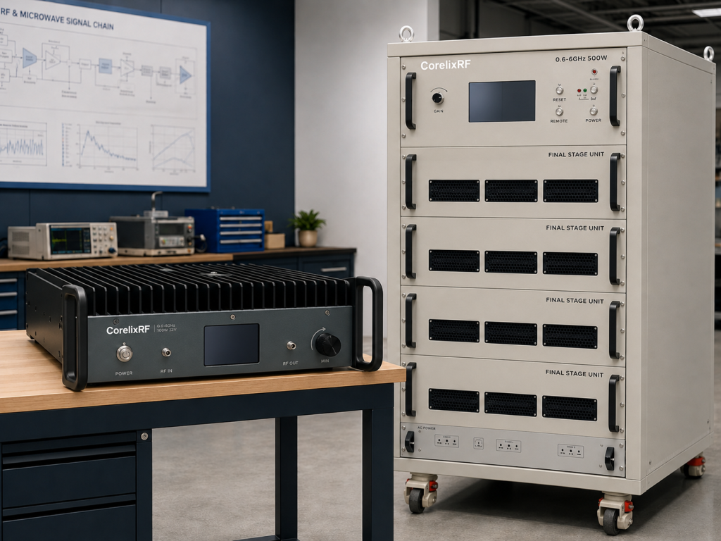
The 100 W version is specified with 53 dB minimum small-signal gain, N-Female RF input and output, AC 220 V supply, forced-air cooling, RS485/LAN control, real-time temperature and current monitoring, and alarm protection functions. The 500 W version increases rated output power to 500 W, lists 60 dB minimum gain, uses N-Female input and 7/16 output, requires AC 380 V supply, and moves to liquid cooling in a 900 x 565 x 1300 mm cabinet. Those differences matter before a purchasing team compares price or lead time.
Start With the EMC Test Path
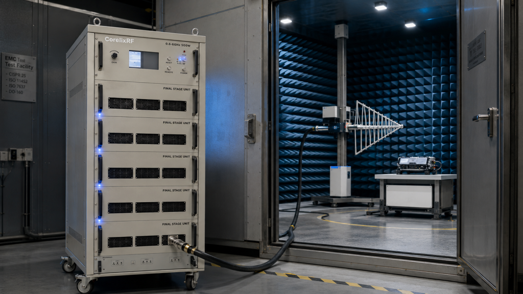
For conducted RF stress, the amplifier may drive injection clamps, couplers, attenuators, limiters or a fixture. For radiated immunity, it may drive an antenna path where chamber loss, antenna gain, cable loss, coupler coupling factor and field probe behavior decide the final level at the equipment under test. A broadband RF power amplifier gives coverage, but the test path determines whether 100 W is enough or whether the 500 W class is more realistic.
When the lab needs frequent setup changes, the 100 W rack-mount unit may be easier to integrate. When the application needs more field strength, higher path loss margin or a demanding antenna/load condition, the 500 W cabinet platform gives more headroom but requires more planning around power service, cooling and floor space. Neither option should be treated as a universal substitute for a system calculation.
This table also explains why selection should involve RF engineering, mechanical design and facilities planning at the same time. A 500 W amplifier can reduce the need for multiple lower-power paths, but it adds cooling and installation requirements. A 100 W rack unit can be cleaner for bench validation, production screening or moderate-power testing.
What to Review Before Requesting a Datasheet
The key inputs are target frequency range, required field or conducted power, waveform type, CW or modulated operation, duty cycle, antenna or load condition, connector preference, control interface and available cooling. For a custom RF amplifier review, include any chamber, antenna and coupler data because the amplifier output power alone does not describe the final RF environment.
The datasheets also list monitoring and protection functions: temperature and current monitoring, optional forward/reverse power monitoring, LAN remote monitoring, over-temperature protection, over-drive protection, over-voltage protection, and VSWR protection with alarm functions. These are important for EMC setups because load conditions may change as antennas, fixtures or cable paths are moved.
Integration Notes for Automated Labs
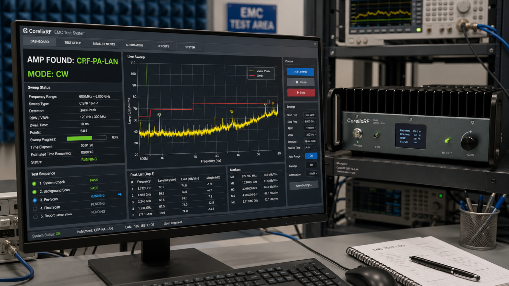
RS485/LAN control lets the amplifier become part of a repeatable test workflow. A lab can log frequency, source level, amplifier gain state, alarm status and temperature while the system sweeps. When forward/reverse monitoring is included, the operator can also catch mismatch behavior before it damages downstream hardware or corrupts test results.
Cooling should be treated as a measured test variable. The 100 W model uses forced air, so rack spacing and airflow direction matter. The 500 W model uses liquid cooling, so coolant infrastructure, cabinet placement and service access should be reviewed before purchase.
Where This Amplifier Class Fits
A 0.6-6 GHz platform fits laboratories that need one RF chain across cellular, ISM, C-band-adjacent, WLAN and general RF stress regions. It also pairs naturally with CorelixRF RF testing and validation workflows where measured output power, gain flatness, spectrum, VSWR and thermal behavior may need review before integration. The best outcome comes from matching the amplifier to the actual bench rather than choosing the largest available wattage.
FAQ
Can the same 0.6-6 GHz amplifier support conducted and radiated EMC work?
Yes, if the surrounding RF path is designed for the intended method. Conducted setups and radiated setups have different couplers, antennas, fixtures, losses and calibration steps.
Why does the 500 W version use a 7/16 output connector?
The local datasheet lists N-Female input and 7/16 output for the 500 W configuration, which is consistent with the need for a higher-power output interface.
Is liquid cooling required for every 0.6-6 GHz amplifier?
No. The 100 W datasheet lists forced-air cooling, while the 500 W cabinet datasheet lists liquid cooling.
What information should be sent for engineering review?
Send frequency range, output power target, operating mode, duty cycle, load or antenna path, connector limits, control interface and cooling constraints.