
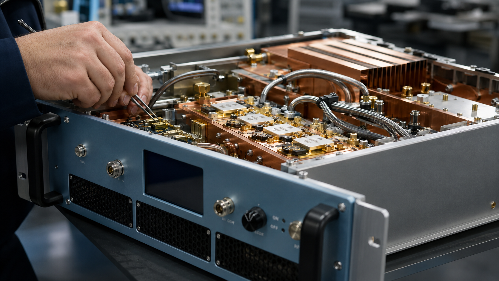
A 9 kHz to 100 MHz LDMOS RF amplifier serves a very different role from a microwave amplifier. At these frequencies, engineers may be working with conducted susceptibility, magnetic-field-related setups, large fixtures, broadband loads or low-frequency RF stress systems. The CorelixRF CRF-PA-9K100M-1000W datasheet gives a concrete platform example: 9 kHz to 100 MHz coverage, 1000 W rated output power, LDMOS SSPA architecture, 60 dB minimum small-signal gain and N-Female RF input/output connectors.
The datasheet positions the amplifier for test and measurement instrumentation, communication systems, RF interference or EW system-level testing and aerospace control environments. That phrasing should be used carefully in public content: it describes application direction, not a promise that one amplifier automatically satisfies a specific standard or installation.
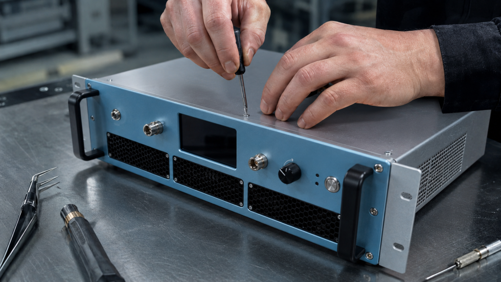
Why the Frequency Range Changes the Selection Conversation
A low-frequency RF power amplifier is often selected for energy delivery into less compact RF structures. Cable routing, load impedance behavior, fixture inductance, grounding and safety boundaries become central. The amplifier is a source of controlled RF power, but the test environment determines whether that power is delivered predictably.
The CRF-PA-9K100M-1000W is specified for a 50 ohm system with 2.0:1 input VSWR, 60 dB minimum gain, +/-4 dB gain flatness and up to 20 dB gain control. That gain control can be useful when the signal source must remain in a clean operating range while the amplifier output is trimmed for a test level.
Protection and Monitoring Should Be Designed Into the Procedure
The datasheet lists real-time temperature monitoring, real-time current monitoring, optional forward/reverse power monitoring, optional LAN remote monitoring and optional input power detection. Protection functions include over-temperature, over-current, over-voltage and VSWR protection with alarms. These functions should be used as part of a documented operating procedure.
For example, a commissioning checklist can include low-level verification, load confirmation, reflected-power review where available, airflow confirmation, alarm-state check, then gradual level increase. This type of workflow is consistent with RF testing and validation practice and helps prevent a one-line power requirement from becoming a risky setup.
When to Consider a Custom Review
Low-frequency high-power systems often involve application-specific limits. The output connector, enclosure access, cooling clearance, interlock logic, control protocol and test documentation may matter as much as the RF output rating. A custom RF amplifier review is appropriate when the lab needs modified control, special documentation, a particular cabinet arrangement or a requirement that is tied to a load that is not a simple 50 ohm termination.
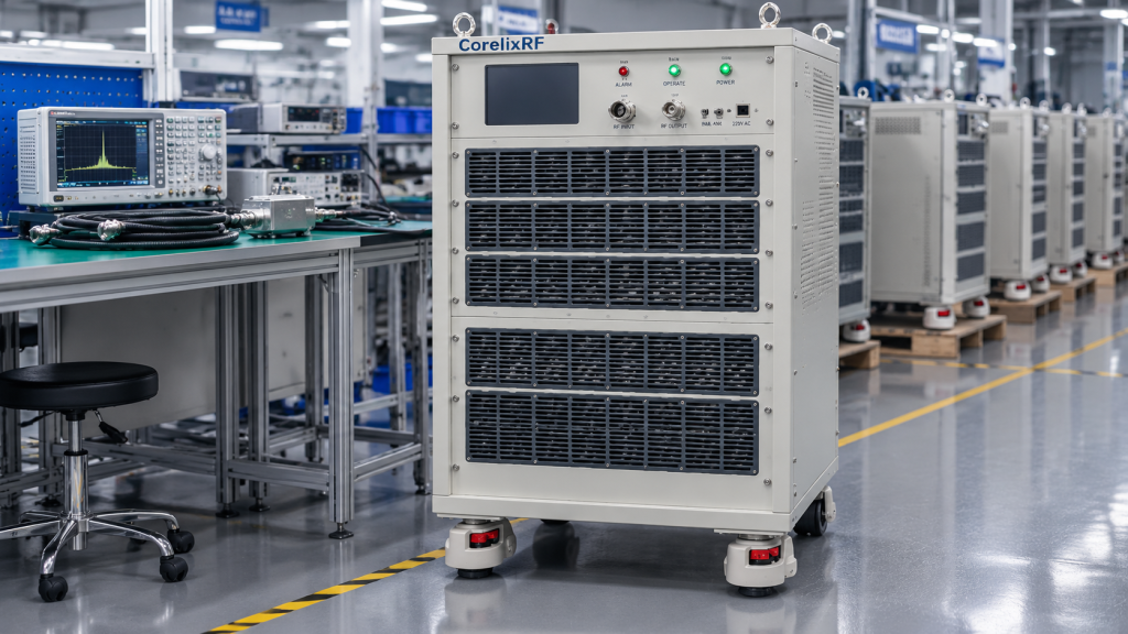
Practical Purchasing Checklist
Before asking for quotation, provide frequency range, required delivered power, waveform or modulation, CW or pulsed use, duty cycle, load description, expected mismatch, facility power, cooling environment, monitoring needs and documentation requirements. If the amplifier will be used inside an EMC laboratory system , include the wider equipment chain because the amplifier is only one part of the compliance or engineering test workflow.
How to Frame the RFQ for Faster Technical Review
A useful RFQ for this class should avoid vague phrases such as high power or broad bandwidth. Instead, write the required frequency span, the lowest acceptable output power at the actual load, the operating profile, the maximum drive available from the source and the expected ambient environment. For a 9 kHz-100 MHz system, it is also helpful to describe whether the amplifier will drive a 50 ohm termination, a fixture, an antenna path, a coupling device or a changing laboratory load.
The local datasheet notes optional forward/reverse power monitoring and optional input power detection. Those options are worth discussing when the bench will be used by multiple operators or when load conditions may change between projects. Monitoring does not replace good RF practice, but it gives the lab more evidence when a run stops, alarms or produces an unexpected result.
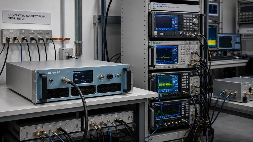
Engineers comparing this platform with a lower-power EMC RF amplifier should also calculate thermal time, cable power handling and duty cycle. A 1000 W source used conservatively can be valuable, but the surrounding path must be built for that level. If the project involves multiple bands, CorelixRF can also review whether a separate broadband RF amplifier platform is more appropriate for the upper-frequency portion of the work.
FAQ
Is 9 kHz to 100 MHz coverage suitable for microwave testing?
No. This is a low-frequency wideband platform. Microwave projects should use the relevant high-frequency or mmWave amplifier path.
What technology is listed for the CRF-PA-9K100M-1000W?
The local datasheet identifies it as an LDMOS SSPA platform.
Does the datasheet include remote control options?
Yes. The listed control interface is RS485 / LAN, with optional LAN remote monitoring noted.
Why is load information important for this class of amplifier?
At 1000 W, reflected power, fixture behavior, grounding and cooling can affect both safety and repeatability.