
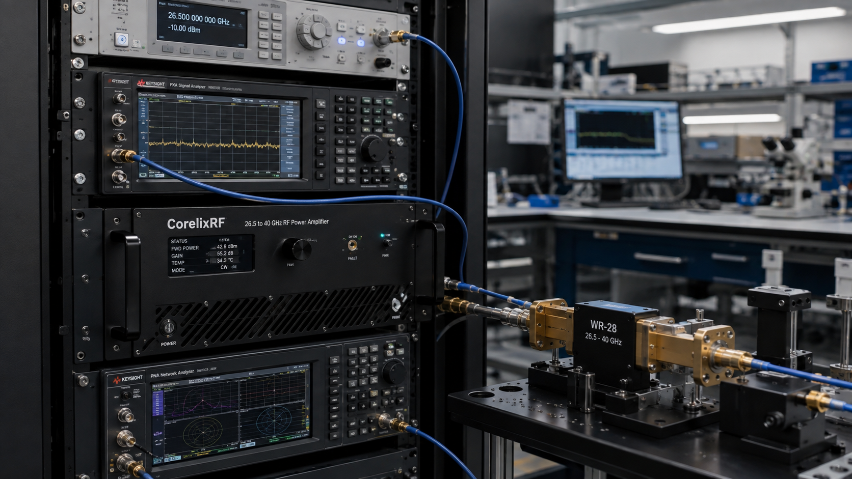
The CRF-PA-26500M40000M-25W is a 26.5 to 40 GHz RF power amplifier for Ka-band test systems, RF interference evaluation, communication subsystem work, and microwave / millimeter-wave integration. The supplied CorelixRF datasheet describes a GaN SSPA platform in a forced-air 19-inch 3U rack-mount configuration with 2.92 mm-F RF input, WR28 RF output, RS485 / LAN control, and 45 dB minimum small-signal gain.
Engineers evaluating a Ka-band RF amplifier often need more than a frequency and power line item. Connector transition, waveguide output, cooling, gain control, monitoring, and fault protection all affect whether the amplifier can be safely integrated into a repeatable test rack.
Why a 26.5 to 40 GHz RF power amplifier needs careful planning
The 26.5 to 40 GHz range sits in Ka-band, where cable loss, connector quality, waveguide handling, and fixture repeatability can dominate test results. A 25 W-class amplifier in this range is a serious RF source. The datasheet headline identifies 25 W rated output power, while the electrical table lists 20 W minimum output power. That should be handled transparently during project review: engineers should confirm the guaranteed output-power definition, test conditions, and production test data for the exact configuration.
The CRF-PA-26500M40000M-25W uses GaN technology and is specified with 45 dB minimum small-signal gain. Gain flatness is listed as -6 to +6 dB, with up to 15 dB gain control range. These values support a controlled millimeter wave power amplifier role where the system controller can adjust levels and monitor operating status.
Core specifications from the datasheet
The operating frequency range is 26.5 to 40 GHz. The listed RF input is 2.92 mm-F, and the RF output is WR28 on the front panel. The control interface is RS485 / LAN. The supply is AC 220 V +/-10%, 50/60 Hz, and typical power consumption is listed as 350 W.
The amplifier is built as a 19-inch 3U rack-mount unit with forced-air cooling. Typical weight is listed as 14.5 kg. Operating temperature range is 0 to +50 C. Harmonics are listed at -10 dBc maximum, spurious response at -60 dBc maximum, input power at 0 dBm maximum, and input impedance / VSWR at 50 ohm / 2:1.
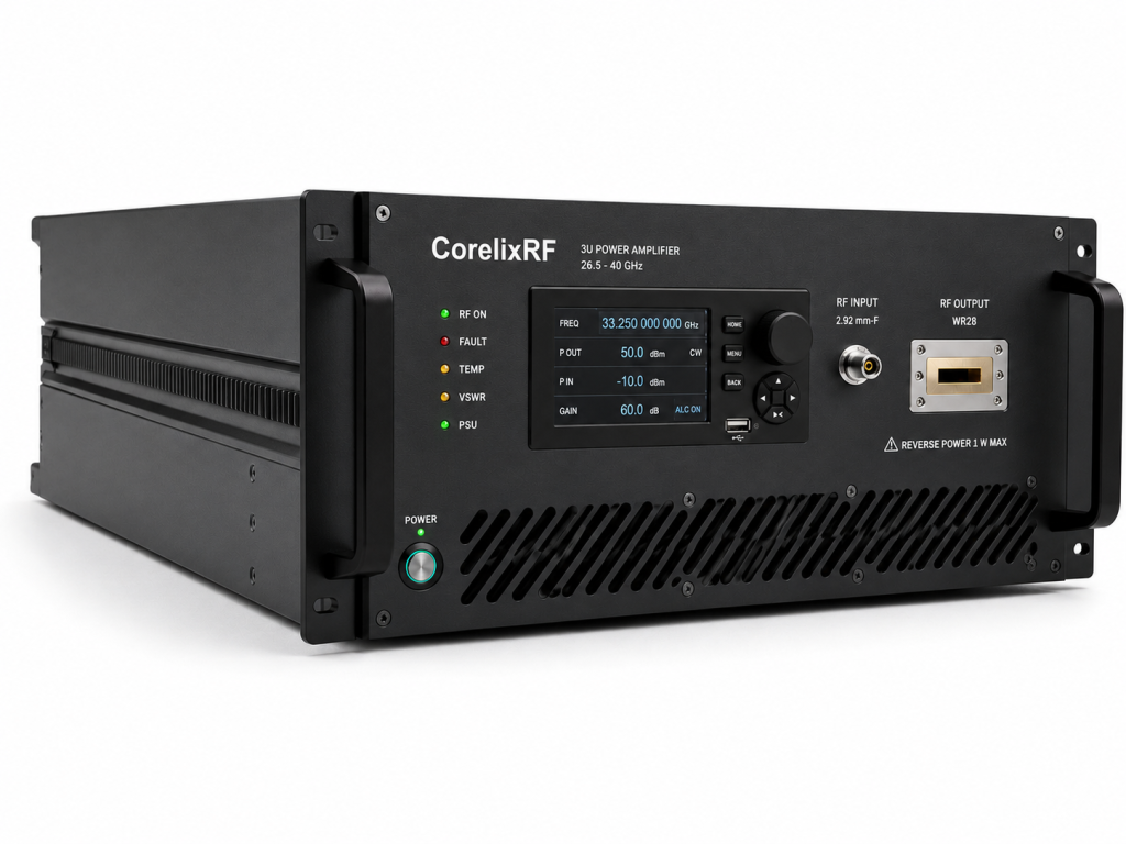
For teams sourcing a rack-mount RF amplifier, these mechanical and electrical values should be reviewed together. Rack depth, airflow direction, waveguide bend radius, interlock design, remote control access, and AC power distribution all matter.
WR28 output and test bench design
The WR28 output is a useful choice for Ka-band power delivery because waveguide can reduce loss compared with coaxial paths at these frequencies. However, it also changes the way the amplifier is integrated. The system must include suitable waveguide transitions, loads, couplers, switches, or antenna interfaces rated for the intended power and frequency range.
If the amplifier is used for RF interference / EW system-level testing, engineers should also consider measurement receiver protection, directional coupler directivity, calibration at the DUT plane, and controlled shutdown when the load path is open. CorelixRF can review project-specific options through its custom RF amplifier process.
Monitoring and protection
The CRF-PA-26500M40000M-25W includes real-time temperature monitoring, real-time current monitoring, alarm and fault protection functions, over-temperature protection, over-drive protection, over-voltage protection, and VSWR protection with alarm functions. Forward/reverse power monitoring, LAN remote monitoring, GPIB programmable control, and input power detection are listed as optional or project-review items.
These functions are not just convenience features. In a Ka-band rack, a mismatched waveguide connection or improper input level can quickly create risk. Monitoring signals help the operator or automation controller respond to fault conditions in a predictable way.
Best-fit applications
The datasheet lists test and measurement instrumentation, communication systems, RF interference / EW system-level testing, and aerospace control systems. The amplifier may be evaluated for Ka-band transceiver testing, frequency converter validation, antenna range work, controlled RF stimulus generation, and high-frequency component stress testing.
Procurement teams should ask for final mechanical drawings, test data, control protocol information, and output-power confirmation before release. That documentation helps align the RF power amplifier with the final system acceptance criteria.
FAQ
What frequency range does CRF-PA-26500M40000M-25W cover?
It covers 26.5 GHz to 40 GHz.
What RF output connector does it use?
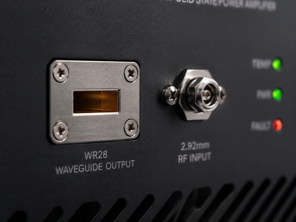
The datasheet lists a WR28 RF output, with a 2.92 mm-F RF input.
Is the amplifier rack mountable?
Yes. The datasheet lists a 19-inch 3U rack-mount configuration with forced-air cooling.
What control interfaces are available?
RS485 / LAN are listed, with optional LAN remote monitoring and project-specific control support where applicable.
What should be confirmed before ordering?
Confirm guaranteed output power, waveform type, duty cycle, waveguide interface, gain-control needs, remote-control protocol, cooling, and fault-handling requirements.