
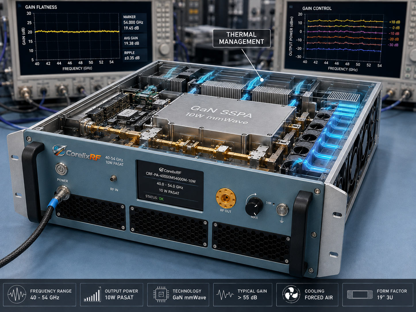
The CRF-PA-40000M54000M-10W is a 40-54 GHz 10W mmWave power amplifier built on a GaN SSPA platform. This datasheet walkthrough explains what each major specification means for integration teams planning WR19 test paths, high-frequency communication hardware validation, component evaluation, and authorized RF subsystem testing.
The model covers 40 GHz to 54 GHz, lists 10 W rated RF output power, uses a 1.85 mm female input and WR19 output, and is described as a 19-inch 3U forced-air unit with RS485 / LAN control. That combination makes it more than a frequency-and-wattage choice. The buyer must also review rack layout, waveguide hardware, thermal airflow, remote-control expectations, and measured acceptance data. For wider context, see CorelixRF’s high frequency RF capability and 18-40 GHz amplifier resources.
Frequency range: 40 GHz to 54 GHz
The 40-54 GHz range places this amplifier above many standard microwave platforms and into a region where waveguide and connector planning becomes central. The range is useful for V band adjacent validation, high-frequency converter paths, component stress testing, and communication hardware development. If a requirement only touches part of the range, the RFQ should state the exact operating points so CorelixRF can review performance expectations realistically.
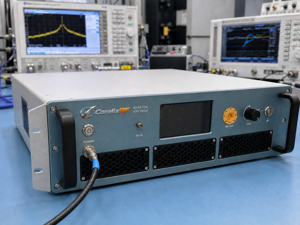
Rated output power: 10 W
Ten watts at 40-54 GHz is enough to require careful load and measurement planning. The output path should use WR19 components rated for the intended power, and the receiving instrumentation should be protected with appropriate couplers, attenuators, loads, and calibration procedures. A 10 W mmWave amplifier should not be treated like a small driver stage simply because the number looks modest compared with lower-frequency power amplifiers.
Gain and flatness
- Small-signal gain: 40 dB minimum
- Gain flatness: -8 dB to +8 dB
- Gain control range: up to 15 dB
These gain figures help determine the source level and the expected output variation across the band. The upstream source should be set so the amplifier is not overdriven. If the test sequence changes frequency automatically, gain-control settings and calibration offsets should be documented. CorelixRF’s RF testing and validation page is a useful follow-up because gain, output power, flatness, spurious response, and thermal behavior should be checked together.
RF interfaces: 1.85 mm input and WR19 output
The input connector supports high-frequency coaxial input, while WR19 output points to waveguide integration. That means the buyer should describe waveguide transitions, couplers, loads, antennas, or fixture hardware before quotation. A clean interface plan prevents avoidable uncertainty during installation and acceptance testing.
Mechanical and control integration
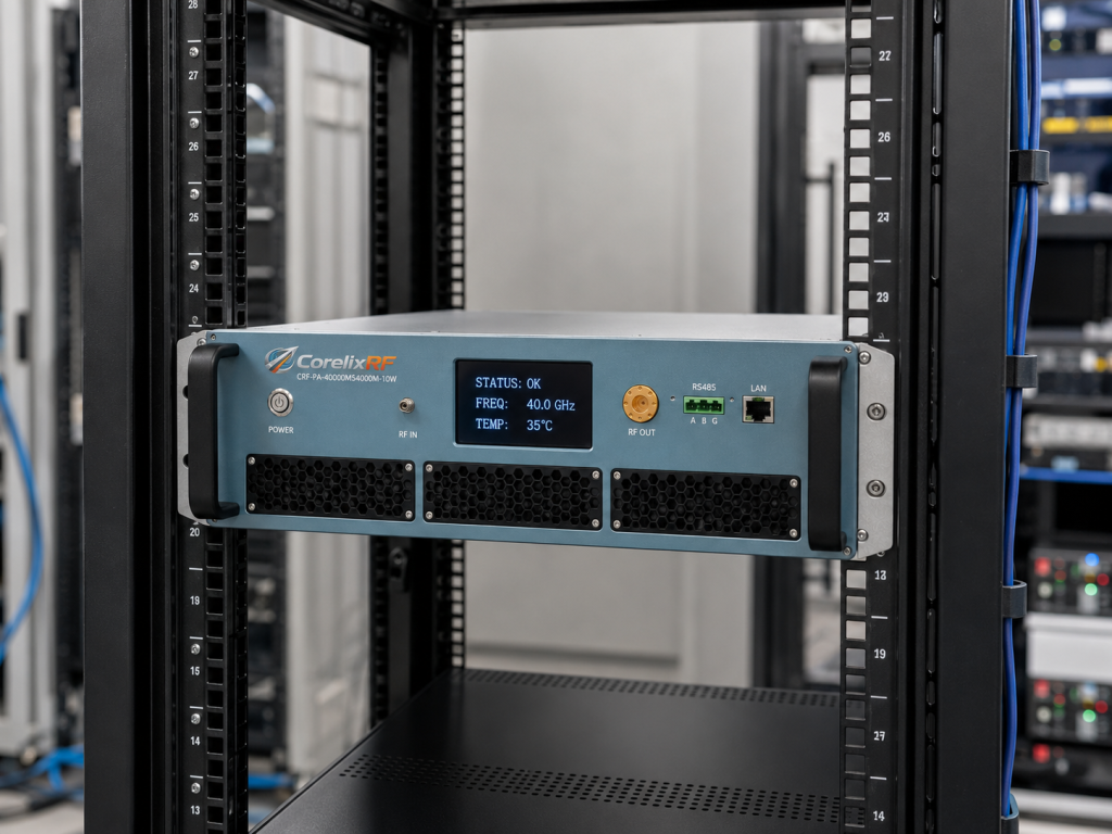
The 19-inch 3U forced-air format makes this model suitable for rack-level test systems. RS485 / LAN control can support automated test sequences, but control behavior should be defined in the RFQ: gain setting, alarm polling, status readback, shutdown behavior, and any interface documentation required by the user’s software environment. CorelixRF’s engineering and manufacturing page gives additional context on the design-to-validation workflow.
RFQ checklist
Send frequency points, output target, source power, waveform, duty cycle, cooling condition, rack constraints, WR19 path details, control preference, monitoring needs, and acceptance-test requirements. If the project may later need higher output or broader coverage, also compare related CorelixRF standard platforms, 6-18 GHz microwave amplifiers, and technical articles on the RF amplifier blog.
FAQ
What is the main product fit?
This model fits 40-54 GHz test integration where 10 W output and WR19 output hardware are required.
What control interfaces are listed?
The supplied specification lists RS485 / LAN control.
Should the WR19 path be defined before quotation?
Yes. Waveguide components, loads, couplers, and transitions should be described in the RFQ.
Does this draft add undocumented certification claims?
No. It stays within supplied product information and general project-review guidance.
Discuss Your 40-54 GHz Amplifier Project
Final engineering review point for CRF-PA-40000M54000M-10W
Before procurement, define the exact operating points, output target, waveform, duty cycle, source level, load condition, control method, cooling environment and acceptance data. For undefined, those details help CorelixRF review the amplifier as part of the actual RF chain rather than as an isolated model number.