
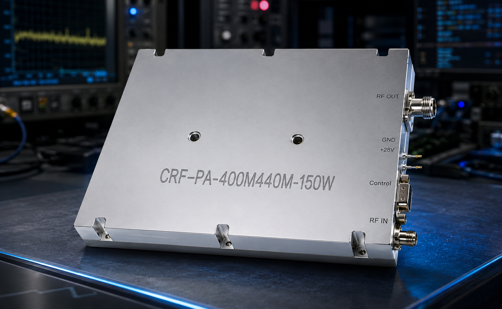
FMEA subject: CorelixRF CRF-PA-400M440M-150W, a 400-440 MHz 150W narrowband RF power amplifier for fixed-band narrowband systems. The datasheet lists 400 to 440 MHz coverage, 120 W minimum and 150 W typical output power, 48 / 50 / 52 dB gain, 20 dB gain adjustment in 0.5 dB steps, SMA-KFD46 RF connectors, D-Sub 15-pin female control connector, pull-core capacitance power input, +24 V to +32 V supply range with +28 V nominal, 22 A typical and 27 A maximum current, 200 x 158 x 25 mm size, 1.4 kg weight, and external heat-sink cooling.
Use this as an initial failure-mode review worksheet. It identifies questions and evidence to resolve for the quoted configuration; it is not a completed FMEA, a verified protection test or a reliability rating.
Failure Mode: Reflected Power
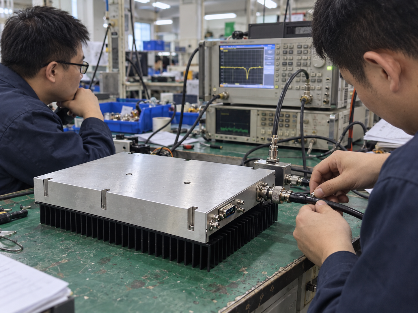
The source lists over-VSWR locked shutdown. A real system-level RF source integration scenario should therefore document the load path, antenna or fixture condition, cable adapters, and reset rule. Protection is not a license to operate into an unknown mismatch.
Failure Mode: Heat Sink Assumption
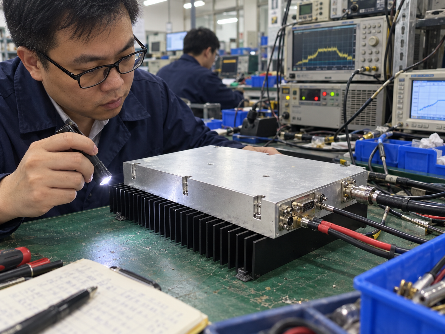
External heat-sink cooling is a project responsibility. In narrowband RF amplification, the heat sink, thermal interface, enclosure airflow, duty condition, and temperature analog output should be part of the receiving record. Include the thermal installation in the RF front-end platform review before closing the heat-removal risk.
Failure Mode: Supply Lockout
The supply range is +24 V to +32 V with +28 V nominal, and the datasheet lists over-voltage lock above 32 V and over-current lock above 29 A. A real RF test and measurement scenario should record supply setting, current limit, wiring method, and current observed at the selected gain state.
Failure Mode: Version Confusion
The M version is an amplifier module path, while the V version includes internal VCO source and scan function. If a communication-system bench needs source agility, the version decision should be explicit. If the buyer only needs an external source chain, the source model and maximum drive belong in the RFQ.
Failure-Mode Review Worksheet
Every row starts open. Add the actual configuration, evidence reference and agreed disposition during team review. Do not assign severity, occurrence, detection scores or an RPN without an agreed method and supporting inputs.
Action Register
- Confirm whether optional RS485 monitoring/control is required.
- Record Pf/Pr indicator needs before quotation.
- Define alarm reset authority.
- Name SMA-KFD46 reference planes.
- Route special control or mechanical scope through custom RF development.
Assess Consequences Before Assigning Scores
Review what each failure could change in the intended system: output level, test validity, component condition, operator action or recovery time. Agree on the consequence and existing controls before rating the risk. A datasheet protection entry is evidence of a listed function, not proof that the installed system has passed the required fault test.
Connect source setting, gain, load, heat-sink condition and reset procedure in each event record. Without those conditions, the team may be unable to distinguish an integration problem from expected protection behavior.
In communication-system evaluation, the realistic scenario is controlled enable behavior and repeatable gain state. In system-level RF source integration, the realistic scenario is whether the M/M1 external-source route or the V internal VCO route should be quoted. In RF test and measurement, the realistic scenario is recording enough evidence to explain a trip without guessing later.
FMEA rule: every optional control or monitoring function must be named before quote release, not assumed after a fault.
Control Evidence
Control evidence should be attached to each FMEA row. If RS485 is selected, the record should show the command state and returned status. If analog Pf/Pr indicators are used, the team should define how the 0 to 3 V indication is captured. If the VCO source version is requested, the source-control method should be listed with the same seriousness as output power.
Reset Policy
The reset policy should define who can clear an alarm, what source level must be restored first, and which measurements must be repeated after a trip. Attach that procedure to the relevant FMEA rows so the next operator can follow the approved recovery checks.
The final FMEA record should travel with the quote so protection behavior, source ownership, and reset authority remain visible during integration.

FAQ
What frequency and output power are listed?
The datasheet lists 400 to 440 MHz coverage, 120 W minimum output, and 150 W typical output.
Which protections are listed?
The source lists over-temperature shutdown/recovery, over-VSWR locked shutdown, over-voltage lock above 32 V, and over-current lock above 29 A.
What real applications fit this article?
Narrowband RF amplification, communication systems, RF test and measurement, and system-level RF source integration fit the source categories.
Can protection entries be treated as completed FMEA controls?
Not without configuration and verification evidence. Assign an owner, obtain the applicable limits and response, and close the row only after the team accepts the supporting record. Leave unverified controls and scores open.