
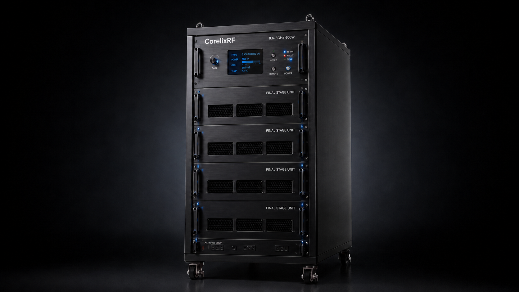
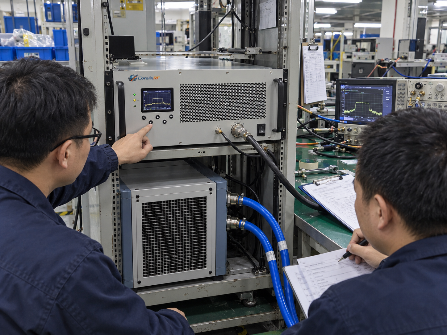
Integrating the CorelixRF CRF-PA-600M6000M-600W requires an agreed liquid-cooling interface, a heat-load basis and a verified response to cooling faults. Its 600 W RF output rating is not a cooling-capacity specification. Before selecting a chiller or enabling RF, confirm the thermal requirements for the exact delivered configuration and assign responsibility for the amplifier, coolant loop and facility heat rejection.
The available June 2026 V1.0 datasheet lists 600–6,000 MHz coverage, 600 W rated RF output, liquid cooling and a project-specific mechanical configuration. It does not specify coolant composition, required flow, pressure limits, inlet-fluid temperature or heat rejected to the coolant. Those items must be resolved in the project interface document.
1. Establish the Equipment and Heat-Load Boundary
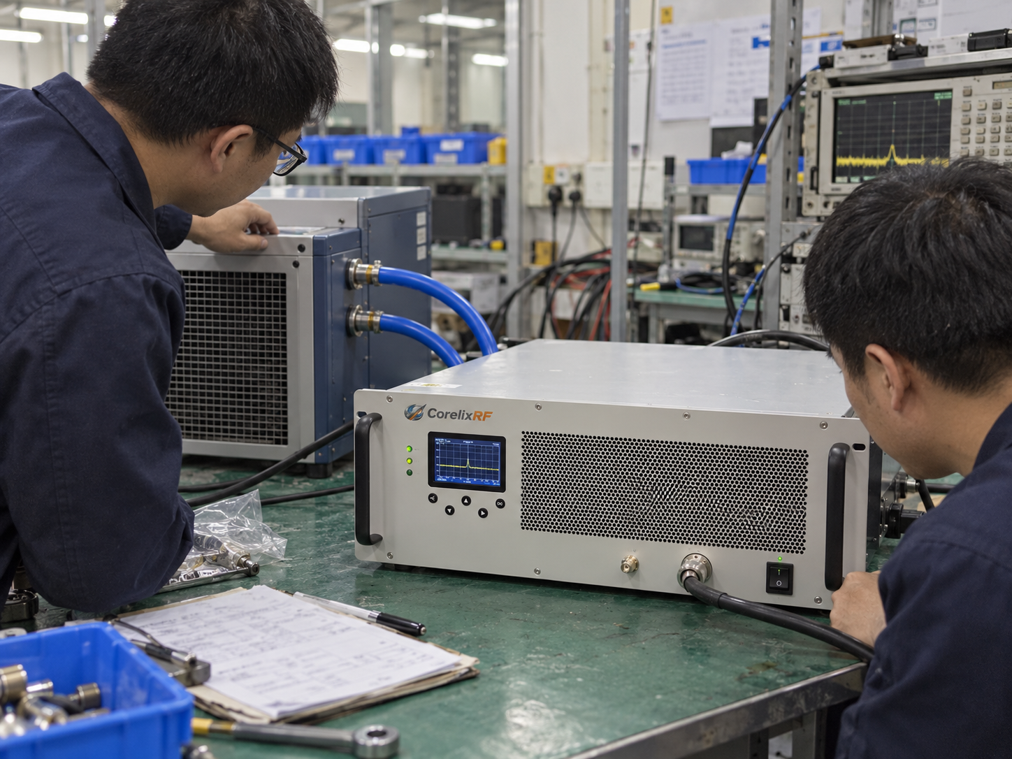
Draw the amplifier, power supply boundary, coolant connections, external chiller or heat exchanger, RF load and associated controls. Mark which equipment is included in the amplifier delivery and which belongs to the installation. A cooling loop that removes heat from the amplifier must also reject that heat somewhere outside the loop.
At a defined boundary and thermal steady state, electrical input and absorbed RF input that do not leave as RF output become heat. For this AC-powered configuration, use real input power at the same frequency, waveform and output condition as the RF measurement. Do not infer electrical consumption from the AC voltage rating, or assume that all system heat enters the liquid loop. The supplier must identify heat released to coolant and heat released to the surrounding air.
Request a thermal-load envelope covering the planned frequencies, output levels, waveform, duty condition and run duration. Ask how startup, standby and auxiliary loads are represented. If only one operating-point measurement is available, retain that limitation when choosing a cooling system. The RF amplifier cooling guide explains the general heat-budget boundary; the interface record below addresses this liquid-cooled configuration.
2. Agree on the Liquid-Cooling Interface
The following table is a project-review worksheet. It defines the information to obtain, not additional specifications or features of the amplifier.
| Interface item | Supplier information required | System integration responsibility | Release evidence |
|---|---|---|---|
| Heat rejected to coolant | Load envelope and applicable operating conditions | Match cooling-system capacity at the actual facility conditions | Approved load basis and cooling-system selection |
| Coolant and materials | Permitted fluid, concentration and wetted-material compatibility | Specify the fill, servicing and contamination-control procedure | Agreed fluid specification; presently unconfirmed |
| Flow and pressure | Required flow envelope, pressure drop, pressure limits and measurement locations | Verify the installed loop, hoses, fittings and monitoring arrangement | Approved hydraulic interface and measured installation record |
| Inlet-fluid temperature | Permitted range and associated operating restrictions | Control the supply temperature and assess condensation at the site | Temperature limits and environmental review |
| Mechanical connections | Final connection drawing, service access and mounting requirements | Route and support the loop without obstructing RF or electrical access | Accepted installation drawing and inspection record |
| Cooling-fault signals | Available signals, meanings and supported response for the quoted build | Assign the controller and any external monitoring needed | Agreed interface and fault-response verification |
Assign a named owner and an open/closed status to each row. Where a capability is not included in the amplifier, identify the external provision or keep the requirement open. A listed temperature monitor does not prove that coolant flow, leak detection or inlet-fluid temperature is monitored.
3. Keep RF, Electrical and Control Conditions in the Same Record
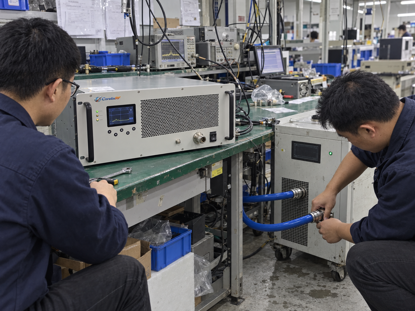
The datasheet lists AC 380 V ±10% supply, N-Female RF input, 7/16 RF output, 60 dB minimum small-signal gain, −5 to +5 dB small-signal gain flatness and 0 dBm maximum input power. The electrical table specifies a 50 Ω system, rated AC input supply and the standard production test configuration. Its note makes the values subject to final production test and project-specific customization. The input limit is not a recommended startup setting, and small-signal gain does not establish linear output power for a particular modulated waveform.
State whether the required RF power is at the amplifier’s 7/16 connector or after the external cable, coupler and load path. Record losses and the measurement reference plane. Cooling verification must use the same defined RF state, rather than a power figure taken from an unrelated setup.
RS485/LAN appears in the control-interface table. Temperature and current monitoring are listed, while forward/reverse power monitoring and LAN remote monitoring are optional. The customization section also lists optional GPIB, LAN remote control and project-specific protocol support. Confirm the supplied functions, sensor locations and command definitions; the interface name alone does not establish which readings or interlocks are available.
4. Define Startup, Fault and Recovery States Before Testing
Agree on the operating sequence with the supplier and system integrator. The states below are proposed acceptance requirements to review; they are not a verified description of the amplifier’s firmware or an instruction to induce a fault.
| State to define | Required decision | Evidence to capture |
|---|---|---|
| Ready with RF disabled | Which verified cooling and control conditions permit an RF-enable request? | Permissive inputs, signal validity and responsible controller |
| RF operation | Which operating envelope and monitored limits apply to this run? | Frequency, drive, output, waveform, duty condition, temperatures and coolant conditions |
| Cooling or communication fault | Which unit detects the event, what response is required, and how is it reported? | Approved test method, time-aligned status, RF response and event log |
| Recovery | What must be corrected and checked, who can authorize reset, and what prevents unintended restart? | Cause, corrective action, reset authority and repeated checks |
The datasheet lists over-temperature, over-drive, over-voltage and VSWR protection, but does not establish their thresholds, timing or complete recovery logic. Obtain configuration-specific details. Do not assume that a coolant-flow trip or automatic restart is built in. Cooling-fault verification needs an approved method and acceptance limits before execution.
5. Verify a Representative Installation
Build the verification plan around the intended installation: final mounting, coolant route, RF load, facility conditions, control software and neighboring equipment. Identify operating points expected to create the largest thermal demand and explain how they were chosen. Define the run duration and stabilization criterion in advance.
Use a single run record linking the amplifier serial number and revision to the cooling-system configuration. Record frequency, input drive, RF output and reference plane, waveform, duty condition, supply measurements, relevant temperatures, flow and pressure where required, alarm state and elapsed time. Record sensor locations and calibration information so a later reviewer can interpret each reading.
Set pass limits before the run. Acceptance should establish the required RF performance under the agreed cooling conditions, rather than only the absence of an alarm. Record interruptions and deviations as well as successful measurements. Component-level results do not by themselves demonstrate a complete EMC test field or a certified system result.
6. Close the Thermal Integration Package
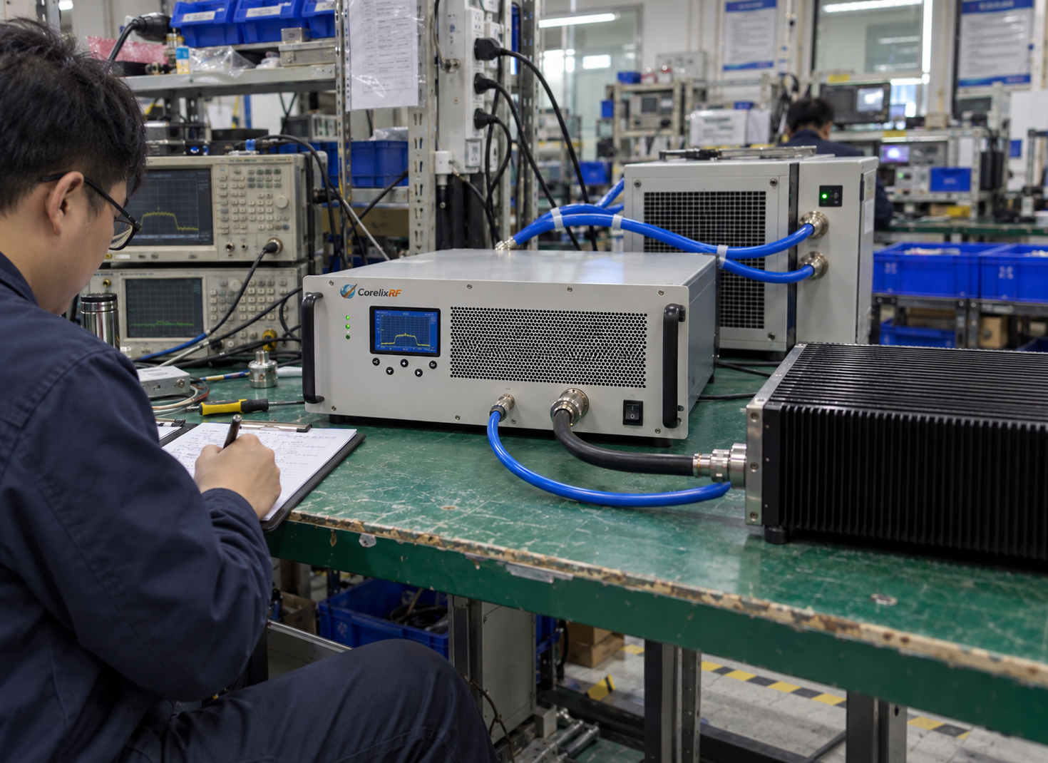
The package is ready for engineering acceptance when it contains the approved heat-load basis, liquid-interface table, installation drawing, control-state requirements, representative verification plan and open-item list. Keep commercial attachments concise: exact configuration, required options, delivery documentation and the party responsible for each remaining input.
For a project review, send CorelixRF the liquid-cooling interface and operating requirements, including the intended frequency range, RF power reference plane, waveform, duty condition, facility cooling and mechanical constraints.
Frequently Asked Questions
Does 600 W RF output mean the cooling system should remove 600 W?
No. Cooling capacity must be based on the heat rejected by the defined equipment at the intended operating conditions. The available datasheet does not provide that heat-load value.
Can the coolant flow or inlet temperature be chosen from this datasheet?
No numerical limits for those items are provided in the available document. Request an approved liquid-interface specification for the delivered configuration.
Are all monitoring and remote-control functions standard?
No. The document distinguishes listed monitoring functions from optional forward/reverse power monitoring and remote-control features. Confirm the exact quoted options and protocol.
What prevents the installation from being accepted?
An unresolved heat-load basis, coolant interface, fault response or verification limit leaves the thermal installation unproven. Record the open item, owner and required evidence before acceptance.