
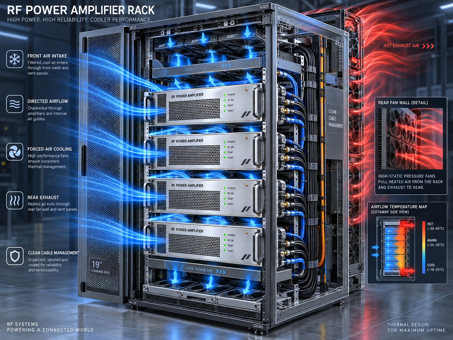
A rack drawing can show that an amplifier fits while leaving the most important installation question unanswered: where will the heat go during the longest operating run?
The answer starts with the operating profile. RF power amplifier cooling requirements depend on electrical consumption, RF output, duty conditions and the thermal path into the surrounding equipment. Output wattage alone cannot size a heatsink or establish the ventilation a rack needs.
Begin with two different installation responsibilities
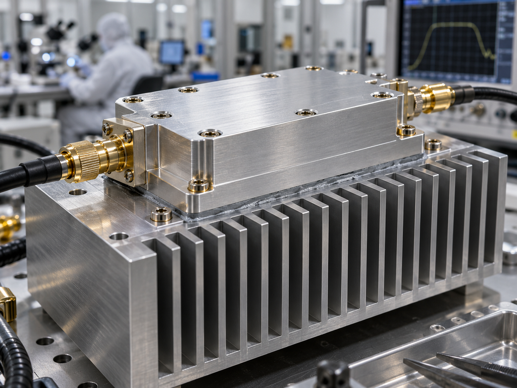
The CorelixRF CRF-PA-2000M18000M-20W-M is a 2–18 GHz module with 20 W listed output, a 28 V DC supply and dimensions of 200 × 100 × 23 mm. Its datasheet explicitly requires an external heatsink. The system designer must provide the thermal installation that the module depends on.
The CRF-PA-1000M6000M-200W lists 1–6 GHz operation, 200 W rated output and a 28 V DC supply. Its 400 × 300 × 80 mm enclosure uses forced-air cooling. Here, the integration task includes supplying suitable inlet air and providing an unobstructed exhaust route.
Both datasheets list an operating temperature range of 0 to +50 °C. Neither available document defines a complete installation envelope through a maximum baseplate temperature, required airflow, thermal resistance or output derating curve. Those additional conditions matter before claiming full-power operation in a particular cabinet.
Build the heat budget before choosing hardware
For a defined equipment boundary at thermal steady state, heat generation is approximately electrical input plus absorbed RF input minus net RF power leaving that boundary. When RF input is negligible and the output is well matched:
Heat dissipation ≈ electrical input power − RF output power.
For a DC-powered module, electrical input requires voltage and current measured at the same operating point. For a complete AC-powered unit, use real input power and account for which auxiliaries fall inside the boundary. Voltage alone does not establish consumption.
Consider a hypothetical module drawing 100 W of electrical power while delivering 20 W of RF output. Neglecting its small RF input, the estimated heat is 80 W. This is a worked example only; the CorelixRF 2–18 GHz datasheet does not specify the current needed to make that calculation for the actual model.
If a hypothetical allowable baseplate temperature were 70 °C and the relevant cooling-air temperature were 40 °C, an 80 W heat load would allow a total baseplate-to-air thermal resistance of at most:
(70 − 40) / 80 = 0.375 °C/W.
That budget includes interface resistance as well as the heatsink path and would require design margin. The temperatures and resulting resistance are not CorelixRF limits. Mini-Circuits’ thermal-analysis guidance explains the relationship between dissipation, temperature rise and heatsink thermal resistance [1].
Follow the heat out of the module
For an externally cooled module, examine the full mounting arrangement. Flatness, contact area, interface material and fastening method affect the route from the baseplate to the heatsink. A large heatsink does not compensate automatically for a poor thermal interface.
The next boundary is the air around the heatsink. If it sits inside a crowded cabinet, room temperature may be a poor description of its operating environment. Nearby power supplies and amplifiers can raise the local inlet temperature before the cooling air reaches it.
For the forced-air 1–6 GHz unit, keep cable bundles and neighboring equipment clear of the actual ventilation path. Confirm the airflow direction and clearance requirements from the installation drawing. The overall enclosure dimensions do not define those clearances.
Fit the cooling concept to the operating schedule
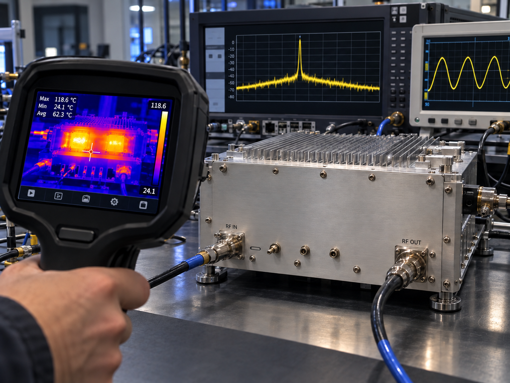
Continuous test operation creates a sustained thermal demand. A CW RF power amplifier used for a long dwell or repeated measurements should be evaluated after temperatures have stabilized, not only during a short room-temperature demonstration.
For a rectangular pulse train with negligible RF output between pulses, average RF output is peak output multiplied by duty cycle. Electrical consumption does not necessarily follow the same scaling because bias and auxiliary loads may remain present between pulses. Pulse duration and transient thermal behavior also matter.
That distinction is relevant to radar test systems and other installations using a high power pulsed RF amplifier. It does not establish pulse ratings for the two products discussed here. Their applicable waveform and operating conditions need model-specific confirmation.
In multichannel communications testing, simultaneous channel operation can make the cabinet’s total heat load more important than any individual amplifier rating. In scientific instrumentation, a repeatable temperature may be needed to limit measurement drift. Each case changes what should be recorded during the thermal test.
When does liquid cooling enter the discussion?
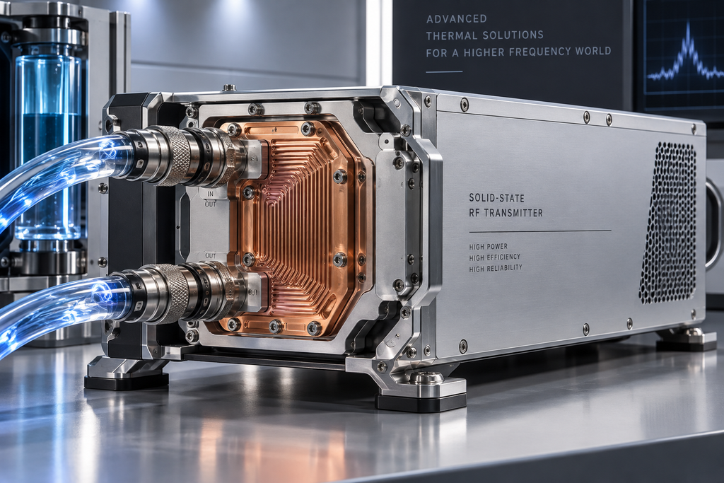
Air cooling can be practical where ventilation, space and environmental conditions support the heat load. Liquid cooling introduces a different set of requirements: coolant temperature and flow, pressure, material compatibility, leak management and maintenance access.
There is no universal RF-output threshold at which liquid cooling becomes mandatory. Packaging and facility constraints can drive the decision. Neither example datasheet establishes a liquid-cooled configuration, so it should be treated as a separate engineering question rather than an available option assumed from output power.
Prove the installation during a representative run
A useful verification run reproduces the intended output, frequency, waveform, duration and surrounding equipment load. Record electrical consumption, relevant temperatures, RF output stability and any alarms. Include the frequency or operating points expected to create the largest thermal demand.
The 1–6 GHz datasheet lists temperature and current monitoring plus over-temperature protection. Confirm how those readings are accessed and what their sensors represent. An internal temperature value is not automatically a case, baseplate or semiconductor-junction temperature.
Treat a thermal alarm or protective shutdown as evidence that the installation needs investigation. Protection is not a substitute for an operating thermal design. Acceptance should include the ability to sustain the required RF performance, rather than merely avoiding a fault message.
The most useful package for a CorelixRF thermal review is a rack layout accompanied by duty conditions, local inlet temperature, available cooling and the intended operating duration. Those details connect the amplifier specification to the installation in which it must work.