
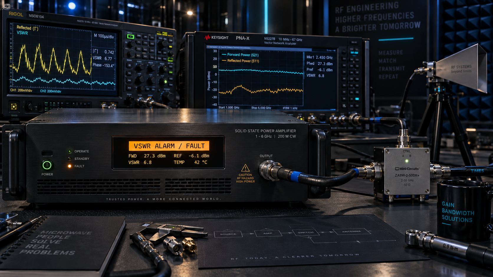
An amplifier runs normally into a matched test load. After it is connected to an antenna through a cable and RF switch, an alarm appears during part of the frequency sweep. Output drops, yet the source setting has not changed.
This hypothetical troubleshooting situation has several possible causes. The amplifier may be responding to a changed load, but a cable fault, switching condition or unrelated thermal event could produce a similar symptom. The useful first step is to connect the alarm to measured conditions, rather than immediately increasing drive or resetting the equipment.
Follow the changed path
Replacing the test load changes what the amplifier sees. An antenna’s input impedance can vary with frequency. A cable changes the phase of the returning reflection and introduces loss. A switch adds another connection and can briefly present a different condition while changing paths.
Record the frequency, forward and reflected measurements, temperature, source level and switch state at the event. Establish whether the fault repeats at the same point. A frequency-specific event suggests a different investigation from an alarm that appears only after prolonged operation.
RF amplifier reflected power protection must be assessed at a defined reference plane. A reading near the antenna and a reading at the amplifier output are not automatically equivalent when a lossy feed line separates them.
What does a VSWR number tell you?
VSWR describes the magnitude of mismatch. For a given reference impedance:
Reflection-coefficient magnitude = (VSWR − 1) / (VSWR + 1).
Reflected-to-forward power ratio = reflection-coefficient magnitude squared.
At 2:1 VSWR, approximately 11.1% of the incident power is reflected at that reference plane. At 3:1, the fraction is 25%. These are calculated ratios, not protection thresholds. The relationship is used in amplifier-selection guidance from AMETEK CTS .
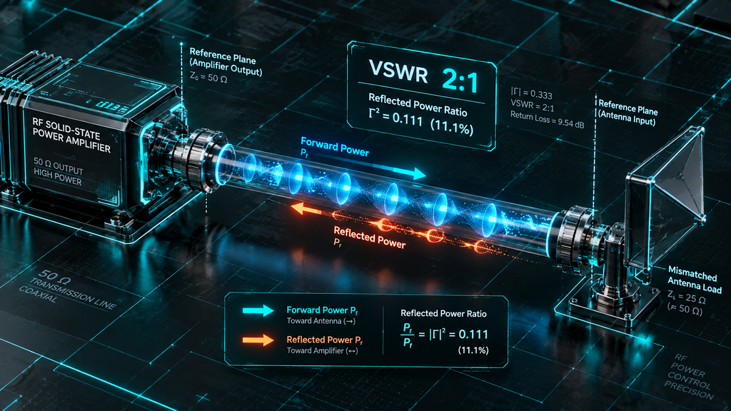
For example, if actual forward power is 200 W at a plane where VSWR is 2:1, the corresponding reflected power is approximately 22.2 W. This is a hypothetical calculation. It does not establish that a particular amplifier can withstand that condition, and forward power itself may change when protection acts.
Mismatch phase also matters to the electrical conditions presented to an amplifier. A complete tolerance statement therefore needs more than a single ratio: frequency, power, duration and applicable phase conditions should be identified.
Read the CorelixRF specification at the right port
The CRF-PA-1000M6000M-200W datasheet lists 1–6 GHz operation, 200 W rated output, 53 dB minimum small-signal gain, SMA-F input and N-F output. It also lists VSWR protection and alarm functions, temperature and current monitoring, and optional forward/reverse power monitoring.
Its “50 Ω / 2:1 max.” entry is under input impedance / VSWR. That is an input-match specification. It is not a statement that the output can operate into a 2:1 load at full rated power under every condition.
The available document does not state the output mismatch threshold, response time, foldback curve or reset logic. Those details should be obtained for the selected configuration before writing a system acceptance requirement. Similarly, detection pins shown in an interface table do not establish calibrated power readings or their availability when monitoring is listed as optional.
An alarm can lead to different operating outcomes
Protection behavior affects the measurement or process that the amplifier supports. The following are general mechanisms to ask about, not confirmed behaviors of the CorelixRF example:
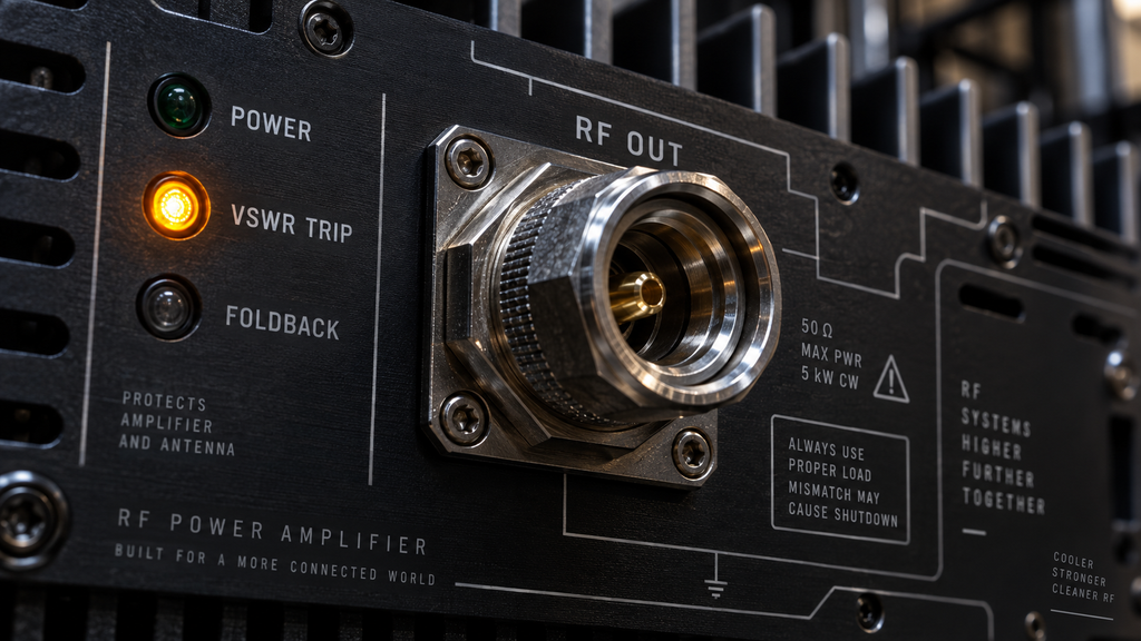
- Foldback reduces output while a fault condition is present. A test may continue running but fail to reach its required level.
- Shutdown removes RF output. The test sequence needs to recognize the interruption.
- Latched shutdown requires a deliberate reset after the fault is addressed.
- Automatic recovery may restore operation when conditions improve; the controller must account for any interruption or repeated cycling.
“Protected” is therefore only the beginning of the discussion. An RF amplifier for EMC testing may need to report that the commanded field-producing power is no longer available. A research system may instead need a fault to stop the entire experiment until an operator reviews it.
Three situations worth distinguishing
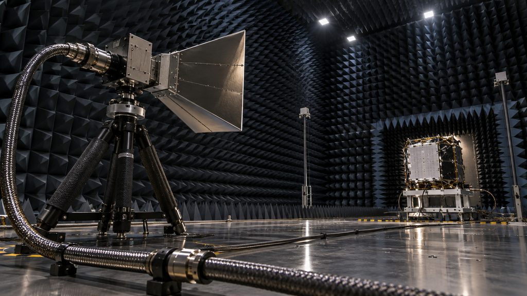
In an EMC radiated-immunity setup, changing antenna match across frequency can alter the demand on the amplifier. Qualification still depends on the complete antenna, chamber and measurement chain, and on the applicable test procedure. A broadband power rating alone does not establish a field-strength capability.
In antenna characterization, a path change can introduce a temporary or persistent mismatch. Check whether RF must be disabled during switching and follow the component manufacturers’ switching conditions. A normal reading after switching does not describe what happened during the transition.
In RF materials or plasma research, the load may change as the process develops. Such applications require a purpose-selected amplifier and, where appropriate, matching equipment. They illustrate why load dynamics matter; they are not a claim that the 1–6 GHz example is suitable for every industrial process.
Close the investigation with an acceptance record
Before accepting the installation, agree on the permitted load envelope, monitored quantities, trip behavior and recovery procedure. Define how the control system detects loss of output and prevents invalid test data from being treated as a successful run.
Use a manufacturer-approved method for mismatch verification. An improvised open- or short-circuit test is not equivalent to a documented qualification procedure.
For a CorelixRF project review, provide the antenna or load data, cable and switch arrangement, required power and acceptable interruption behavior. These inputs help turn a general protection feature into a system requirement that can actually be checked.