
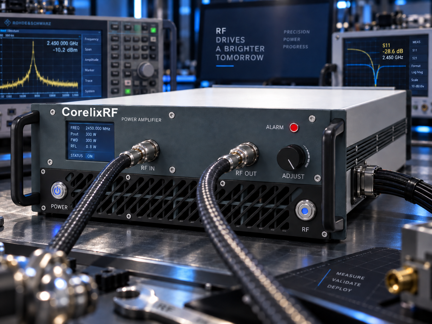
The amplifier has not changed, but the test bench has. A new signal generator replaces the original source, a driver stage is added, or an automated routine restores an old power setting. The next startup now begins with a different signal at the amplifier input.
This is where RF amplifier input overdrive protection becomes a system-integration question. A protection feature is useful, but the source settings, cable losses and control sequence still need to keep the input within the permitted operating envelope.
The following commissioning workflow uses the CorelixRF CRF-PA-2000M18000M-20W-M as a product example. Its datasheet specifies 2–18 GHz operation, 20 W output power, 43 dB minimum small-signal gain and a maximum listed input power of 0 dBm. The module uses a 28 V DC supply, SMA-F RF connections and a 7W2 control connector. It requires an external heatsink.
Establish the boundary at the input connector
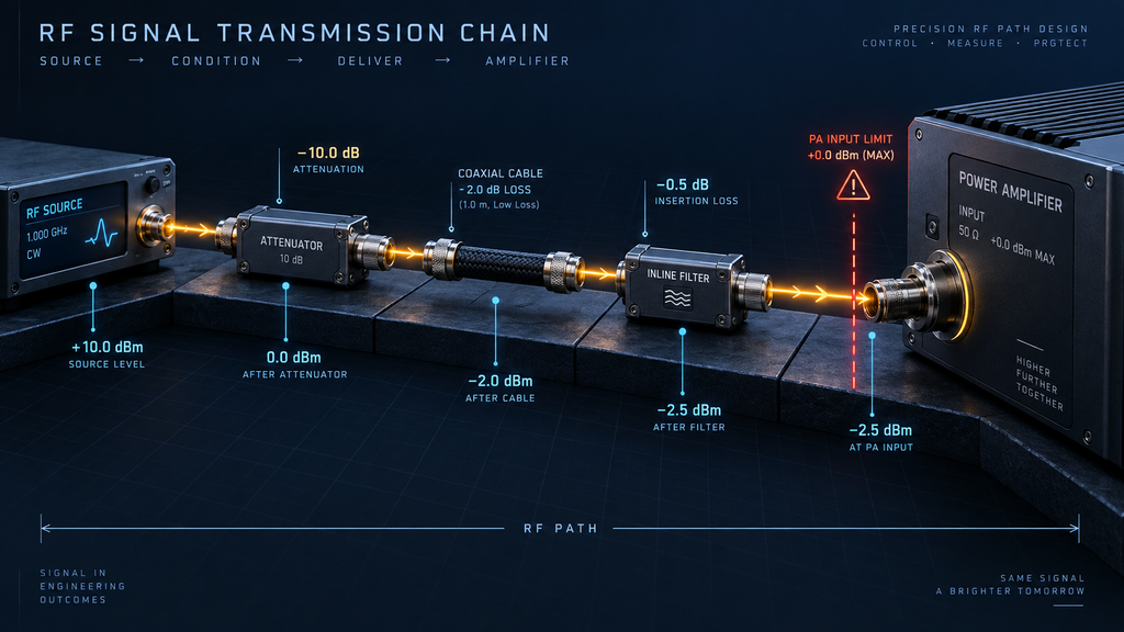
Before selecting a source level, draw the actual chain:
Signal generator → optional driver → attenuator → cable → amplifier input.
For an approximately matched chain, the nominal input estimate is:
PA input (dBm) ≈ source output (dBm) + upstream gain (dB) − path loss (dB).
The amplifier sees the result at its connector, not the number displayed on the generator. Include frequency-dependent loss and the uncertainty of the source and measurement arrangement. Keysight’s power-amplifier test software similarly treats the PA input-power limit and input-path loss as separate settings .
A hypothetical chain with a −10 dBm source, 6 dB driver gain and 2 dB total loss produces approximately −6 dBm at the amplifier input. This is an illustrative calculation, not a recommended startup level or a measured result for the CorelixRF module.
Separate the input numbers that have different meanings
The drive needed for a target output, the maximum specified operating input and an absolute damage limit are not interchangeable.
The available CorelixRF table lists 0 dBm in the maximum input-power column. It does not provide a separate destructive-input rating or a protection threshold. Do not assume the module can safely tolerate an unspecified amount above 0 dBm simply because over-drive protection appears in its feature list.
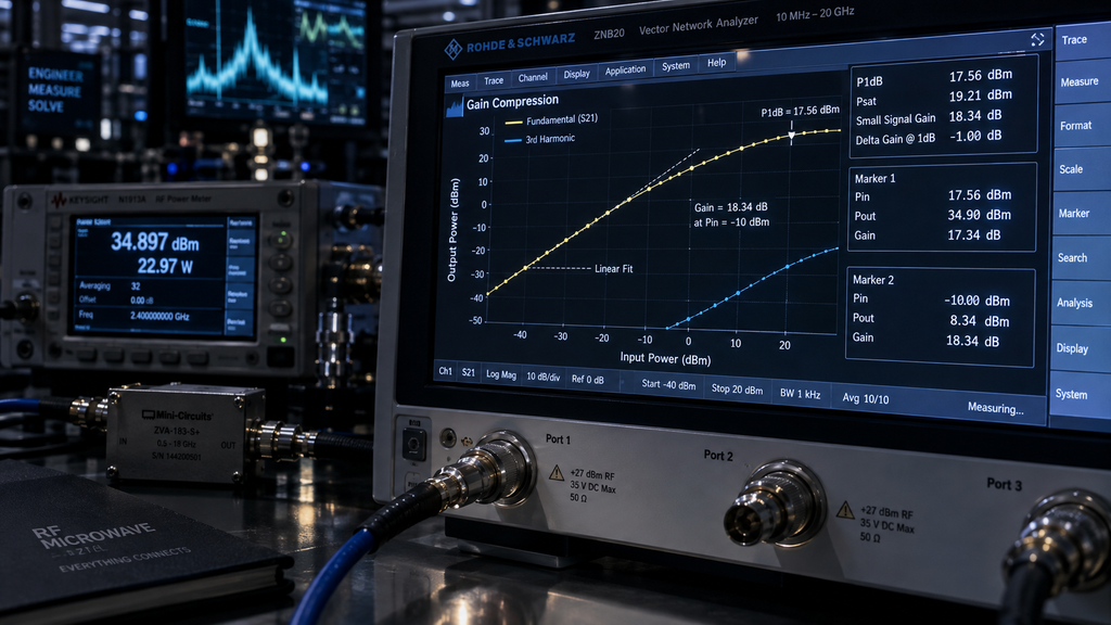
Likewise, using the 43 dB minimum small-signal gain to estimate drive does not establish the exact drive for rated output. The operating gain can differ from small-signal gain as the amplifier approaches compression. Keysight describes compression as a reduction relative to the linear gain reference .
Prepare the output and thermal paths before applying RF
Connect a suitable load through components rated for the intended frequency and power. Confirm measurement attenuation before connecting sensitive instruments. Install the required heatsink and verify the supply and control connections against the approved configuration documentation.
For this 2–18 GHz module, the external heatsink is part of the integration requirement. Its compact 200 × 100 × 23 mm dimensions do not imply that free-air operation is adequate.
Use the equipment-specific enable and supply sequence. A connector type alone does not define pin assignments or timing; obtain those details before connecting an automated controller.
Increase drive while watching the response
Begin with RF disabled and a conservatively low, verified source setting. After the required power and enable sequence, raise drive in controlled increments while staying within the documented input limit.
Compare each input change with the output response. If output stops increasing as expected, pause the ramp and investigate. Compression is one possibility; a control setting, supply limitation, thermal condition or protection event can also change the response.
For this model, the datasheet lists temperature and current monitoring. Forward/reverse power monitoring is optional, so an integration plan should not assume those measurements are available in every delivered unit. External instrumentation may be needed for commissioning.
Repeat the checks where the system changes behavior
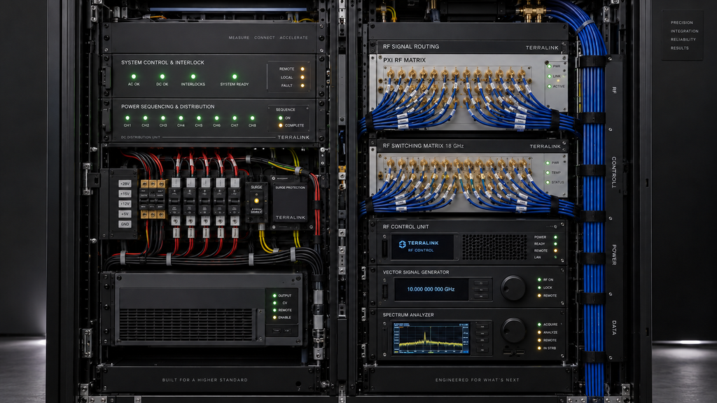
A single measurement at one frequency does not validate a broadband test routine. Check relevant band edges and points where the source, driver or signal path changes behavior. Frequency compensation must remain subject to the amplifier input limit.
For communications testing, verify the actual modulated waveform. A source’s average-power setting does not fully describe peak envelope behavior. For pulsed laboratory work, confirm peak level, pulse timing and the amplifier’s approved operating conditions before extending a single-tone setup.
In production test equipment, also inspect transitions between test steps. A safe steady-state level does not establish safe behavior during a preset recall, range change or restart.
Make restart behavior part of the handover
The final handover should describe what happens after a source reboot, controller disconnect, interlock event or amplifier fault. Store an explicit low-power initialization state and verify that software cannot silently restore an unsuitable level.
Document the measured input-path loss, source limits, enabled options and approved startup sequence. Keep those records with the test configuration so that replacing a cable or driver prompts a review of the drive budget.
This approach supports automated test stations, communications development and research instrumentation without tying the amplifier to one end application. The practical deliverable is a repeatable input condition each time the system starts.
When discussing a CorelixRF integration, send the source’s maximum output, upstream gain, cable losses, waveform and control sequence. These details are more useful for reviewing input drive than the desired output wattage alone.