
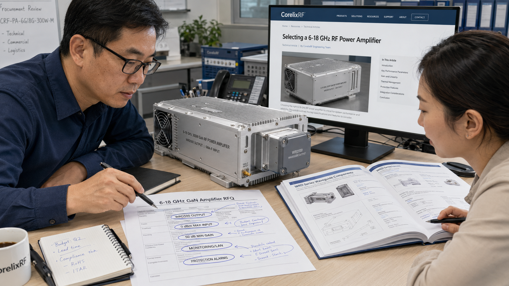
A 6-18 GHz 300W GaN RF power amplifier is usually selected after a chain-level problem appears: the signal source is clean but underpowered, the test range needs more margin at the load, or the system integrator needs one high-power microwave stage across a wide C/X/Ku-band span. The CRF-PA-6G18G-300W-M gives engineers a concrete review point with 6-18 GHz operation, 300 W rated output power, 50 dB minimum small-signal gain, SMA-F input, WRD500 output, optional LAN control, DC 28 V +/-5% power input, and forced-air cooling in a 320 x 230 x 120 mm mechanical configuration.
The first engineering question is not whether 300 W sounds sufficient. It is where that power must exist. If the target is at the amplifier output, the review is direct. If the target is at a horn antenna, fixture, chamber reference plane, or waveguide load, the calculation must include transitions, couplers, waveguide runs, mismatch, and measurement uncertainty. CorelixRF’s related 6-18 GHz GaN RF amplifier content is useful for framing that system-level review.
Engineering Decision 1: Output Interface
The WRD500 output is not a minor line item. It determines downstream waveguide hardware, adapter planning, load selection, and mechanical support. A coaxial input through SMA-F can be straightforward, but the output path should be drawn before procurement. If the system already uses waveguide components, WRD500 can simplify the high-power side. If the system is mostly coaxial, the transition losses and ratings need attention.
Engineering Decision 2: Drive Level and Gain Margin
The specification lists 0 dBm maximum input power and 50 dB minimum gain. That means the driver and source chain should be controlled, not casually connected. Add fixed attenuation where needed, define software limits, and decide whether the amplifier is enabled only after the source is stable. For swept testing, include leveling strategy and dwell behavior in the RFQ.
Engineering Decision 3: Protection Behavior
CorelixRF specifications describe temperature and current monitoring, alarm protection, and project-ready control interfaces. For this power class, reflected power is not an abstract risk. A loose transition, wrong load, or antenna mismatch can change operating conditions quickly. Ask how alarm states are reported, how the amplifier is reset, and whether optional monitoring should be included.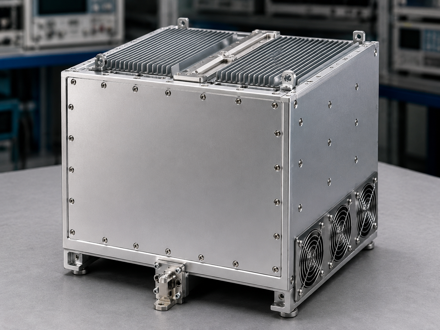
RFQ Notes
A strong RFQ should include frequency points, required power at the measurement plane, waveform, duty cycle, input level, load type, output path, control preference, cooling environment, and documentation requirements. If the project is still comparing alternatives, include the adjacent 6-18 GHz amplifier selection context and ask CorelixRF to review whether a standard or custom path fits best.
Review Sequence for the Engineering Team
A practical review can move in four passes. First, confirm the RF requirement by band segment: required power near 6 GHz may not be the same as required power near 18 GHz. Second, review the output path and decide whether WRD500 hardware, load rating, and coupler placement are already defined. Third, check input protection around the 0 dBm limit so a driver or signal generator cannot overdrive the amplifier during setup. Fourth, define the control and fault workflow before the unit is installed in a rack or chamber.
This sequence gives purchasing a cleaner document to send with the RFQ. Instead of asking only for price and lead time, the buyer can ask CorelixRF to confirm RF output, interface, monitoring, cooling, drawings, and acceptance data. That is especially useful when the amplifier will be used across multiple test programs.
Common Mistakes to Avoid
Do not assume a high power number solves fixture loss. Do not leave the waveguide output path undefined. Do not ignore reflected power during antenna or load changes. Do not write the RFQ without saying whether the amplifier will operate under CW, stepped, swept, or modulated conditions. These are not paperwork details; they determine whether the selected amplifier will behave as expected in the real microwave chain.
Also confirm who owns the final operating procedure. In a high-power microwave chain, the amplifier vendor, system integrator, and lab operator may each assume the other party controls source level or load verification. Put those assumptions in writing before shipment.
Acceptance Review Notes
For this 6-18 GHz 300W amplifier, acceptance should include output checks across the lower, middle, and upper parts of the band, a review of the WRD500 output path, and confirmation that the control and alarm behavior matches the planned test workflow. If the amplifier will be used in more than one lab setup, document the approved cable, transition, coupler, and load combinations. That record prevents later teams from assuming that any waveguide path is equivalent.
The review should also identify whether the amplifier is part of a temporary test setup or a long-term installed system. Temporary setups need stricter operator notes because cables and loads may change often. Installed systems need clearer maintenance access, cooling checks, and documented fault recovery.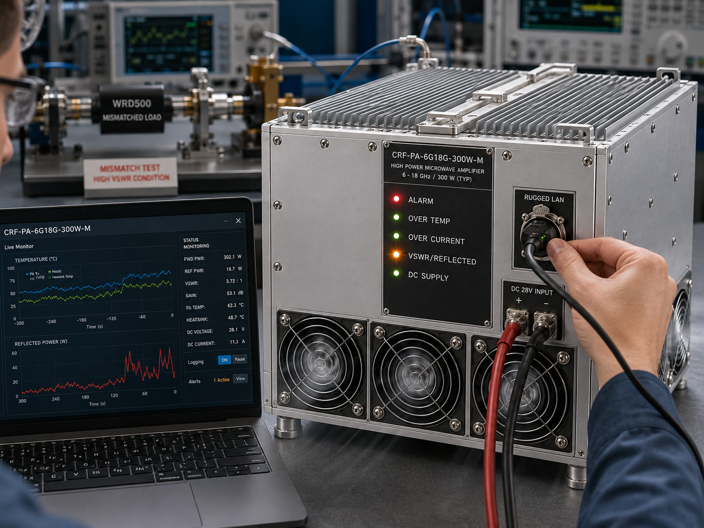
FAQ
Is this 6-18 GHz 300W amplifier a final recommendation?
No. It is a specification-backed starting point that still needs review against the complete RF chain, load, waveform, cooling, and control plan.
Why does the WRD500 output matter?
It affects waveguide hardware, adapter loss, load selection, fixture layout, and safe handling on the high-power output side.
What should buyers send for review?
Send the frequency range, required power at the load, source level, waveform, duty cycle, downstream interface, cooling limits, and control requirements.
Does this article claim stock or certification?
No. It only uses CorelixRF specification details and avoids unverified claims about inventory, certifications, or customer deployments.
For a reviewed configuration, use the CorelixRF Contact page and include the full RF path.