
Specifying an 8-12 GHz 100W X-band RF power amplifier begins with a simple sentence, but it should not end there. The CRF-PA-8G12G-100W-M is specified for 8-12 GHz operation, 100 W rated output power, 52 dB minimum small-signal gain, -3.5 to +3.5 dB gain flatness, N-female input and output connectors, CAN control, DC 28 V input, and a 255 x 245 x 80 mm mechanical configuration. Those details are enough to start a procurement conversation, but not enough to finish one safely.
Start with the job the amplifier must perform. Is it supporting an X-band communication test? Is it boosting a swept test source? Is it part of an RF interference setup? Is the output feeding a load, antenna path, or fixture? Each answer changes the RFQ. A broadband RF power amplifier can fit many test benches, but the final setup should be matched to the chain.
Step 1: Define the Required Output
Write the output requirement at the measurement plane, not only at the amplifier connector. If the requirement is 100 W at the load, calculate cable loss, coupler loss, adapters, and mismatch. If the requirement is amplifier-rated output only, state that directly. This avoids disagreement between the RF engineer, purchasing team, and vendor review.
Step 2: Protect the Input
The specification lists 0 dBm maximum input power. That should trigger a source-control plan. Use attenuation, software limits, or driver-stage review so the input is not overdriven during setup. Gain is valuable only when the signal chain is controlled.
Step 3: Confirm Control and Diagnostics
CAN control is a useful fit for embedded systems and controlled test stations. Before ordering, define the command set expectations, status polling, enable behavior, alarm handling, and fault reset. If the amplifier will be part of a repeatable automated bench, control details deserve the same attention as RF connectors.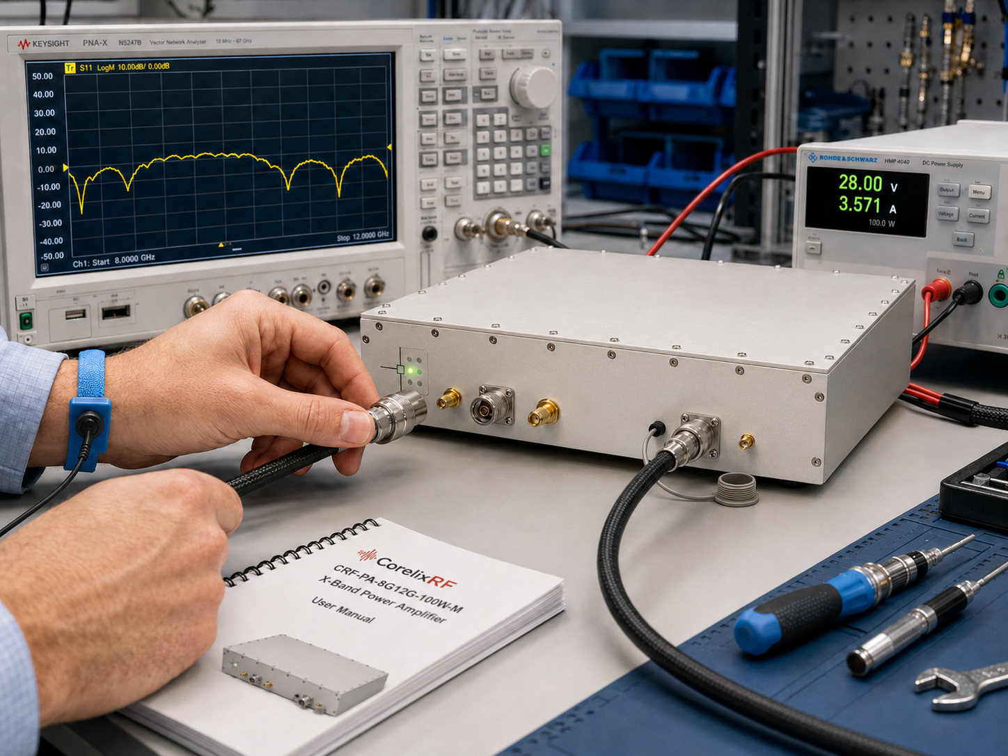
Step 4: Review the Mechanical Envelope
The compact module format is attractive, but it shifts thermal and mounting responsibility to the integrator. Confirm airflow, mounting plate, cable bend radius, connector access, and service clearance. If the amplifier is installed in a rack or enclosure, document the ambient temperature assumption and expected run time.
What to Ask CorelixRF
Ask whether the standard CRF-PA-8G12G-100W-M configuration matches the required band, power, interface, and thermal conditions. If the project overlaps a wider microwave RF amplifier range, include that context. A narrower X-band amplifier can be the better choice when the application does not need extra coverage.
Step 5: Write the Acceptance Test Before Ordering
The acceptance test should be written before the order is placed, not after the amplifier arrives. A simple but useful test plan might include output power checks at several X-band points, small-signal gain verification, control-interface confirmation, alarm-state review, and a thermal run under the expected duty condition. If the lab needs a specific report format, ask for it during the RFQ stage.
Step 6: Decide Whether This Should Be a Module or Rack Build
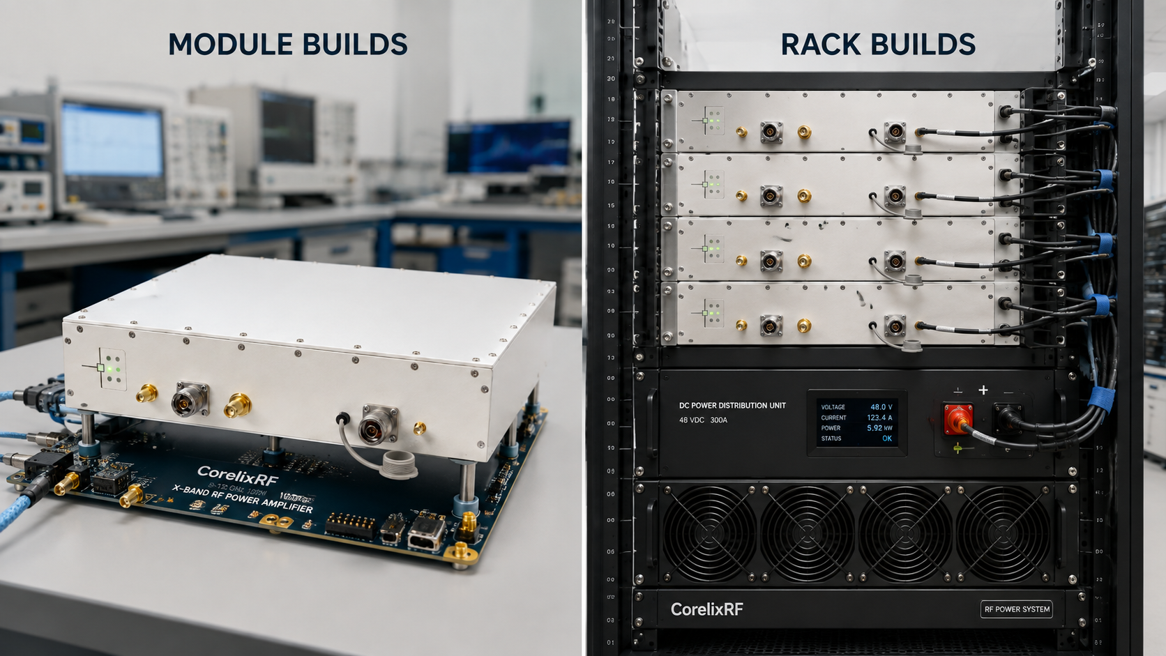
The CRF-PA-8G12G-100W-M is described as a compact module configuration. That can be ideal for OEM integration or controlled lab builds, but it means the buyer must own the surrounding mechanical design. If the amplifier is going into a rack, define the mounting plate, airflow path, cable routing, DC power distribution, and service access. If the project needs a ready rack system, ask whether CorelixRF should review a packaged configuration instead.
A Short Procurement Example
A clear request might say: We need an 8-12 GHz 100 W X-band RF amplifier for automated component testing, with N-female input and output, CAN control, DC 28 V operation, output checks at 8, 10, and 12 GHz, and documentation for internal qualification. That request is much stronger than simply asking for a 100 W X-band amplifier because it identifies the real selection boundaries.
The same request should state whether the amplifier will remain in one bench or move between projects. A mobile lab module needs clearer connector-handling instructions, power cabling notes, and startup checks than a permanently installed system.
For repeat projects, keep a saved configuration sheet with frequency points, gain setting, source limit, cable set, and load. That small record helps the next test run match the first one.
Buyer Handoff Notes
For an X-band module, the handoff package should be specific enough for another engineer to reproduce the first setup. Keep the source limit, attenuation values, DC power requirement, control settings, cable set, and acceptance frequencies in the project file. If the amplifier is later moved into a rack or enclosure, repeat the thermal review instead of assuming the original bench result still applies.
This is also the right time to confirm whether gain control is used during normal operation or only during commissioning. If software changes gain settings during a test, the procedure should log those values with frequency and output measurements.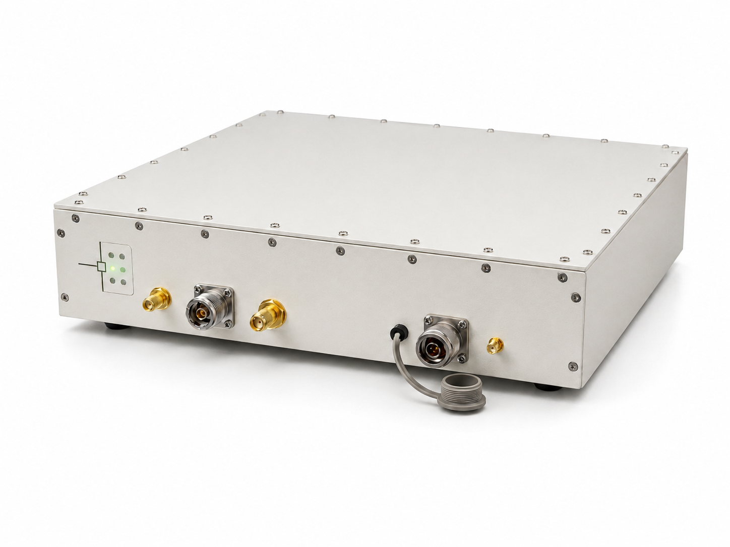
FAQ
What is the focus keyword for this article?
The focus keyword is 8-12 GHz 100W X-band RF power amplifier, and it is used in the title, opening section, and FAQ context.
Why is N-female I/O notable at X-band?
It simplifies some lab setups, but cable quality, adapter choice, and connector handling still affect repeatability at 8-12 GHz.
Should buyers request test data?
Yes, if internal qualification requires it. Ask about final test data, mechanical drawings, and control notes during RFQ review.
Can this be modified for a custom project?
Use the CorelixRF Contact page to request review of connector, control, cooling, or documentation changes.