
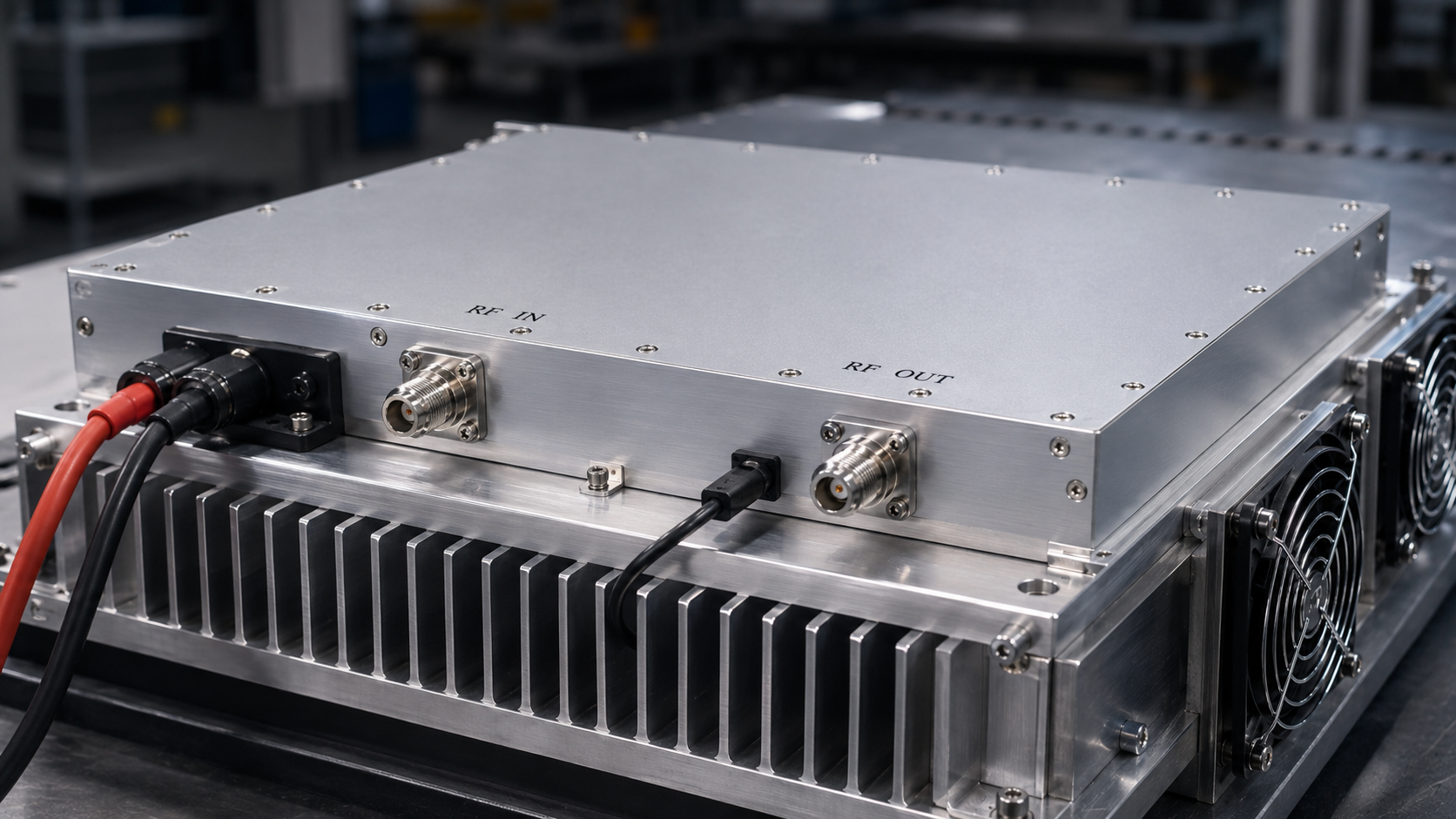
Use this article as an RFQ checklist for the CRF-PA-4K400M-200W-M, a 4 kHz to 400 MHz 200W LDMOS EMC RF amplifier. The specification describes 4 kHz to 400 MHz operation, >=200 W saturated output power, 53 dB minimum small-signal gain, -4 to +4 dB gain flatness, SMA-F input, N-F output, 48 V DC and 12 V DC power inputs, and a 329.5 x 104.8 x 61 mm module configuration.
Unlike a microwave amplifier selection article, the low-frequency RFQ should focus heavily on fixture behavior, load condition, and operating method. At 4 kHz to 400 MHz, the amplifier may interact with injection devices, cables, transformers, or special loads that do not behave like a clean 50 ohm bench setup. CorelixRF’s EMC RF amplifier resources can help frame adjacent low-band requirements.
RFQ Field 1: Frequency Segments
Do not write only 4 kHz to 400 MHz if the project uses a few critical ranges. List the exact bands, dwell points, or sweep behavior. This helps determine whether output power, gain flatness, and thermal behavior should be reviewed at specific points.
RFQ Field 2: Output at the Fixture
State whether the 200 W requirement is at the amplifier output, after a cable, into a transformer, or at another fixture reference point. Low-frequency losses and mismatch conditions can be highly setup-dependent.
RFQ Field 3: Source and Input Protection
The specification lists 0 dBm maximum input power and 50 ohm / 2:1 maximum input VSWR. Add the source level, driver chain, attenuation plan, and any enable sequencing. Protecting the amplifier input should be part of the operating procedure.
RFQ Field 4: Power and Cooling
The module uses 48 V DC and 12 V DC power inputs with rated power consumption around 650 W. The thermal path belongs in the RFQ. Provide host enclosure details, airflow assumptions, mounting plan, ambient temperature, and expected duty cycle.
RFQ Field 5: Monitoring and Documentation
Ask what alarm, temperature, current, and protection information is available in the final configuration. If the project requires drawings, test reports, or internal qualification documents, include that request early. CorelixRF custom RF amplifier engineering review is useful when a module must be adapted to a larger system.
Red Flags in a Low-Frequency EMC RFQ
Several phrases should trigger a follow-up before quotation. Need high power across the whole band is too vague unless the buyer states where that power is measured. Works with our fixture is incomplete unless the fixture impedance and connector path are described. Continuous operation should include run time, ambient temperature, cooling assumptions, and allowable fault response. These details keep the amplifier review grounded in real operating conditions.
Suggested RFQ Format
Use a short table or bullet list when sending the request. Include frequency bands, required output at the fixture, waveform or modulation, source level, input protection plan, output connector, load or fixture description, DC supply availability, cooling method, expected duty cycle, monitoring needs, and required documentation. Attach drawings or photos if the amplifier must fit an existing chassis.
Why This Model Should Not Be Treated Like a Catalog Line
The CRF-PA-4K400M-200W-M is a module with low-frequency coverage and meaningful output power. That combination is valuable, but it also means the host system matters. The buyer should review grounding, cable routing, enclosure design, heat removal, and operator access. A well-defined integration plan is the difference between a useful EMC power stage and a difficult bench retrofit.
Acceptance Notes for Procurement
For acceptance, define several representative frequency points instead of asking for one broad pass/fail statement. Include at least one low-frequency point, one mid-band point, and one upper-band point if those ranges matter to the application. Ask how output power, gain, and alarm behavior will be documented. If the amplifier will drive a nonstandard fixture, request a review of the fixture assumptions before final approval.
A final RFQ should also name the person or team responsible for host-enclosure cooling and power wiring. That responsibility is easy to miss when the amplifier is purchased as a module.
Low-Frequency Validation Notes
A low-frequency EMC amplifier should be validated with the real fixture or a representative load whenever possible. The buyer should define whether the important result is amplifier output power, voltage or current into a coupling device, or a measured field or injection level. These are different acceptance conditions. Stating the desired result early helps CorelixRF review whether the module, power supply, cooling path, and protection behavior match the planned system.
For procurement, avoid combining multiple use cases into one vague requirement. If the amplifier will support conducted immunity, fixture development, and general RF injection work, list those use cases separately. Each may place a different demand on output power, duty cycle, connector handling, and protection response.
For procurement, avoid combining multiple use cases into one vague requirement. If the amplifier will support conducted immunity, fixture development, and general RF injection work, list those use cases separately. Each may place a different demand on output power, duty cycle, connector handling, and protection response.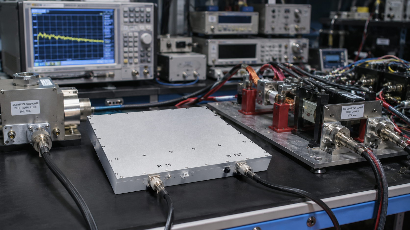
FAQ
Why use an RFQ checklist format for this amplifier?
Low-frequency EMC projects depend heavily on fixture, load, and operating details. A checklist reduces missing assumptions.
Is this model suitable for all EMC standards?
No standard or certification claim is made here. The amplifier should be reviewed against the user’s actual test method and required equipment chain.
What connector details are known?
The supplied specification lists SMA-F input and N-F output. Any connector change should be requested during the engineering review.
Where should the checklist be sent?
Send the completed RFQ details through the CorelixRF Contact page with the application and required band.