
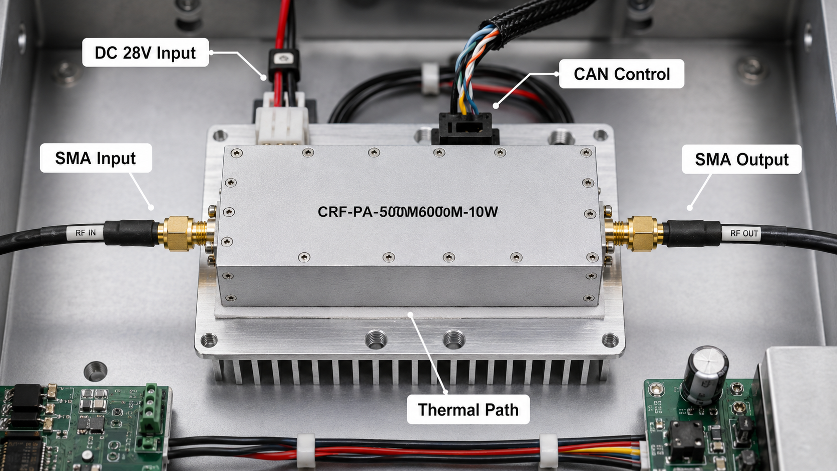
Picture a compact broadband test bench: a signal generator, a programmable attenuator, a switch path, a directional coupler, a load or antenna fixture, and a controller that needs repeatable amplifier behavior. The CRF-PA-500M6000M-10W fits this kind of bench-level problem as a 500 MHz to 6 GHz 10W GaN RF amplifier module. Its specification lists 0.5-6 GHz operation, 10 W rated output power, 40 dB minimum gain, SMA-F input and output, CAN control, DC 28 V power input, and a compact 130 x 85 x 25 mm mechanical package.
This is not the article for a 300 W chamber amplifier. It is about a compact power stage for broadband lab validation, communication experiments, RF interference setup development, and source boosting. If the project later needs much more output, compare this module against a 2-6 GHz RF power amplifier or a higher-power rack configuration.
Application Note: Source Boosting
A 10 W amplifier can be useful when a clean source needs more power before a passive network or device under test. The source level still matters: the module lists 0 dBm maximum input power. Add attenuation and software limits so the source cannot overdrive the amplifier during setup or script errors.
Application Note: SDR and Communication Experiments
For SDR-driven work, the wide 0.5-6 GHz coverage can reduce amplifier changes across multiple bands. The RFQ should describe modulation type, crest factor expectations, duty behavior, and whether the output target is average or saturated power. Do not assume a CW output number describes every waveform.
Application Note: Embedded Test Stations
CAN control makes the module relevant for embedded test environments. Define enable behavior, alarm reads, status polling, and reset logic. If a production-support bench will use the amplifier repeatedly, control documentation can be as important as RF gain.
Practical Integration Notes
The SMA-F connectors simplify compact RF layouts, but cable quality and connector care still matter. The small package also means the host system must handle thermal design. Ask for mechanical drawings and confirm airflow, mounting surface, ambient temperature, and expected run time. Monitoring includes temperature and current information, with project review available for additional requirements.
For broader selection context, CorelixRF’s broadband RF amplifier resources and Contact page can help compare compact modules with rack-level amplifiers.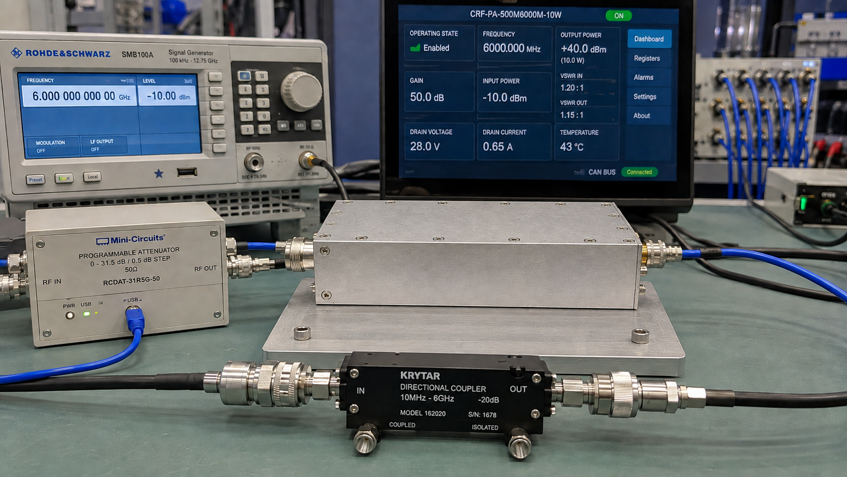
Bench Setup Example
A practical bench might place the CRF-PA-500M6000M-10W after a signal generator and programmable attenuator, then route output through a directional coupler to a device under test or shielded fixture. The controller reads amplifier status through CAN and keeps source output below the 0 dBm input limit. A power sensor or spectrum analyzer confirms output at selected frequency points. This kind of setup makes the amplifier useful for repeatable development work rather than one-off manual tests.
When to Choose Something Larger
If the required output is at an antenna after long cable runs, 10 W may not be enough. If the test must run at high duty for long periods, thermal design becomes more demanding. If the project needs chamber-level field strength, a rack amplifier may be more appropriate. In those cases, use this compact module as a reference point and ask CorelixRF to compare it with higher-power 0.5-6 GHz or 2-6 GHz platforms.
Documentation Worth Requesting
For embedded benches, ask for mechanical drawings, connector orientation, power input notes, control information, and recommended operating limits. If the module will be used by multiple engineers, create a simple operating sheet that states source limits, enable sequence, cooling assumptions, and safe shutdown behavior.
Small Module, Real Integration Work
A compact module can make the bench look simple, but it still needs proper engineering ownership. Someone must define the DC supply, heat path, mounting method, RF cable strain relief, software limits, and operator instructions. If the amplifier is part of a repeatable validation bench, keep the configuration controlled so test results are comparable from week to week.
For handoff, store the source-level limit and CAN-control assumptions with the bench documentation. That helps another engineer reproduce the same setup without guessing.
Repeatable Bench Use
The compact 10W module is most valuable when the bench is repeatable. Save the CAN-control assumptions, source-output limit, cooling arrangement, and calibration points with the test procedure. If multiple engineers use the same setup, label the approved input range and shutdown sequence. Small broadband modules can be reliable development tools, but only when the surrounding bench prevents overdrive and thermal guesswork.
A compact amplifier can also be useful as a reference driver for component comparison. In that role, repeatability matters more than peak power. Keep the same cables, same attenuation, same cooling arrangement, and same measurement points when comparing devices under test.
A compact amplifier can also be useful as a reference driver for component comparison. In that role, repeatability matters more than peak power. Keep the same cables, same attenuation, same cooling arrangement, and same measurement points when comparing devices under test.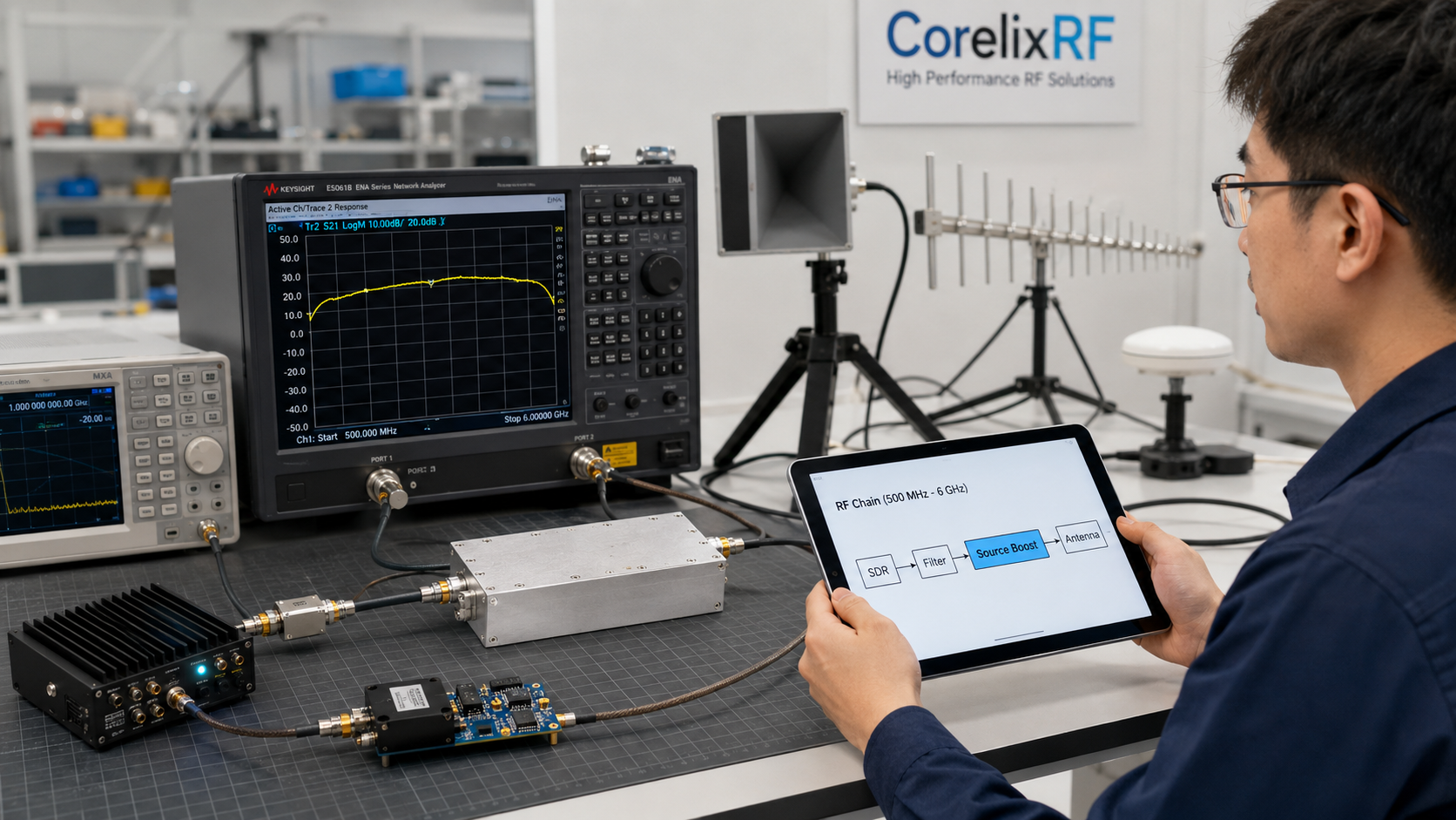
FAQ
Is this a high-power EMC amplifier?
No. It is a compact 10 W broadband module. It may support lab and pre-system work, but high-power EMC requirements need separate review.
What is the key interface detail?
The module uses SMA-F input/output and CAN control, making both RF layout and software-control planning important.
What should an RFQ include?
Include frequency range, output target, waveform, source level, duty cycle, host enclosure, cooling plan, and control requirements.
Are images or external assets required?
No. This draft intentionally contains no images and only uses CorelixRF internal/contact links.