
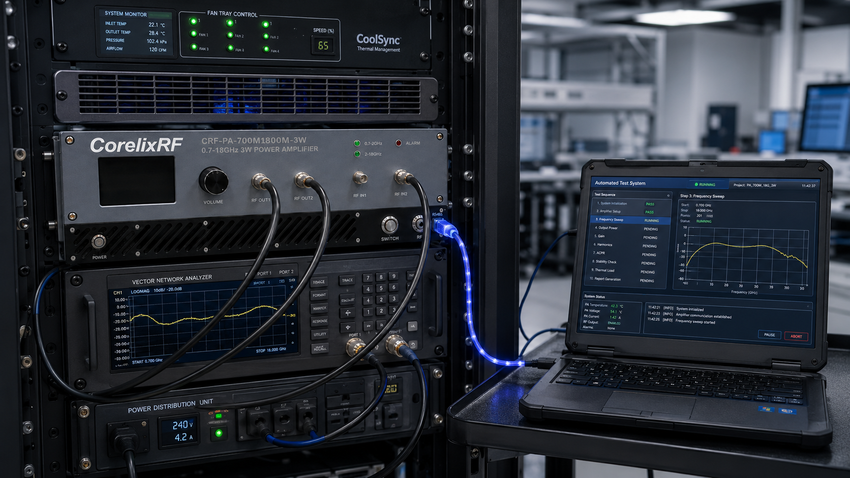
Scenario: an RF lab needs one rack-level amplifier platform to support several broadband experiments. Some work sits around 700 MHz to 2 GHz. Other work moves from 2 GHz to 18 GHz. The lab does not need hundreds of watts; it needs moderate output, wide coverage, control, and repeatability. The CRF-PA-700M18000M-3W is specified for that kind of use case as a 700 MHz to 18 GHz 3W dual-channel RF amplifier.
The specification describes channel 1 from 700 MHz to 2,000 MHz and channel 2 from 2,000 MHz to 18,000 MHz, 3 W output power, 35 dB minimum small-signal gain, 20 dB maximum gain adjustment, SMA-female input and output connectors, RS485 control, forced-air 3U rack mounting, -15 dBc harmonics, -40 dBm/MHz noise floor, and -60 dBc spurious performance under stated conditions.
Scenario 1: SDR Chain Development
For SDR projects, the amplifier can support multiple bands without rebuilding the bench for every experiment. The key is to define channel routing, gain settings, source level, and expected waveform. A SDR RF amplifier chain should include attenuation, filtering, and measurement protection so software mistakes do not become hardware problems.
Scenario 2: Broadband Lab Validation
A dual-channel 700 MHz to 18 GHz platform can help a lab validate components, cables, fixtures, or receivers over a broad range. The RFQ should state whether the amplifier is used for spot checks, swept operation, or repeated automated tests. If the output requirement changes by band, list that instead of using a single summary line.
Scenario 3: RF Interference System-Level Testing
For low-to-moderate power interference simulation, repeatability and control can matter more than maximum output. RS485 control, gain adjustment, and rack mounting help support scripted operation. Ask how alarms, temperature, current, and optional forward/reverse power monitoring are handled in the final configuration.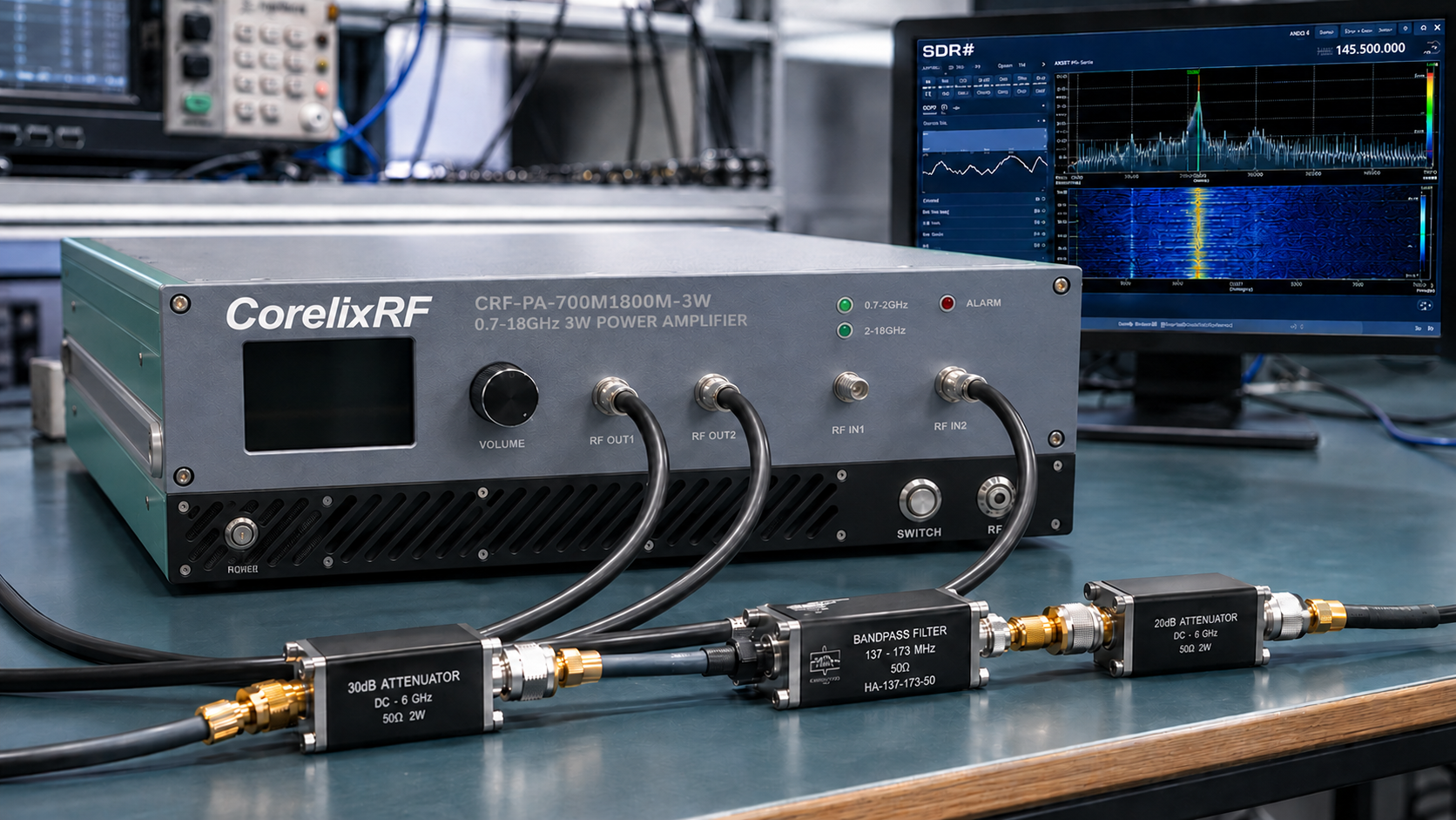
Integration Notes
The 3U rack format simplifies installation compared with a loose module, but airflow, rack spacing, AC power, grounding, and connector access still need review. SMA-female ports are convenient, but cable losses at the upper end of the band can be significant. Define the measurement plane and confirm the required power there.
If the project needs a different band split, more output, or a custom interface, use CorelixRF’s custom wideband amplifier review process. Include the application, source type, frequency plan, output target, control preference, and expected operating time.
Scenario 4: Automated Regression Testing
A dual-channel wideband amplifier can be useful when a lab repeatedly validates RF paths after firmware, antenna, or fixture changes. The test software can step through frequency ranges, set gain, confirm output with a sensor, and log amplifier status. In this use case, maximum power is less important than repeatability, control behavior, and clear channel mapping. Link the amplifier review to CorelixRF RF power amplifier resources when comparing standard and custom choices.
Channel Planning Questions
The RFQ should ask how channel 1 and channel 2 are routed, how the 2 GHz boundary is handled, and whether both paths require the same control behavior. If the bench uses different antennas, filters, or loads by channel, document those differences. A broad model name can hide two very different integration paths.
Operating Procedure Notes
Write a startup sequence that confirms source level, channel selection, load connection, amplifier enable, gain setting, and measurement logging. Write a shutdown sequence that removes drive before disabling the amplifier. These procedures are simple, but they reduce operator mistakes when the same rack is used across many wideband experiments.
Procurement Summary
This model should be purchased as a controlled wideband test resource, not as a generic gain block. The RFQ should describe both channels, expected power by band, gain adjustment use, control software, rack environment, and documentation needs. If the lab later needs higher output in one band, ask CorelixRF whether a dedicated amplifier should be paired with this dual-channel platform.
During review, separate channel-specific requirements from requirements that apply to both channels. That keeps the vendor response clear and prevents one broad frequency range from hiding different operating cases.
This also makes later troubleshooting easier when test results shift between bands.
Channel Documentation Notes
For the dual-channel amplifier, write separate notes for the 700 MHz to 2 GHz path and the 2 GHz to 18 GHz path. Each channel may use different cables, filters, antennas, loads, or calibration points. Keeping the channel plan explicit helps the lab avoid confusing a wide frequency label with a single uniform RF path. It also makes troubleshooting easier when a result changes in only one part of the band.
For SDR teams, record the waveform, bandwidth, average level, and peak behavior used during each test. A 3 W RF output rating is helpful, but modulated signals can create different operating expectations than a simple CW check.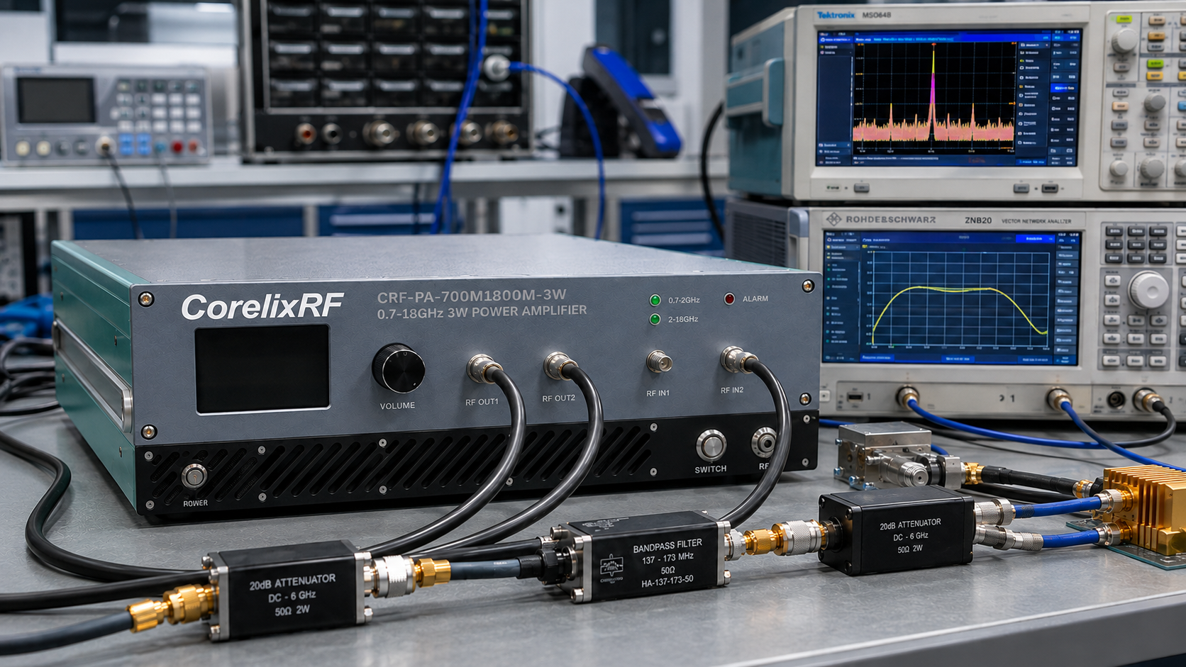
FAQ
Why is this article written as scenarios?
The model is broad and dual-channel, so practical use cases explain selection better than a single generic specification list.
Is 3 W enough for every 700 MHz to 18 GHz test?
No. It depends on the required output at the measurement plane, cable loss, waveform, and device under test.
What makes it useful for SDR work?
Wide coverage, gain adjustment, rack mounting, and RS485 control can support repeatable SDR-driven RF experiments.
Does the article make unsupported claims?
No. It uses only available CorelixRF specification details and avoids stock, certification, or customer-case claims.