
Article format: engineering selection guide. This article is written as a technical selection guide for engineers who are still defining an 18-40 GHz bench. It focuses on decision points, measurement discipline, and when the 5W class is a practical first step.
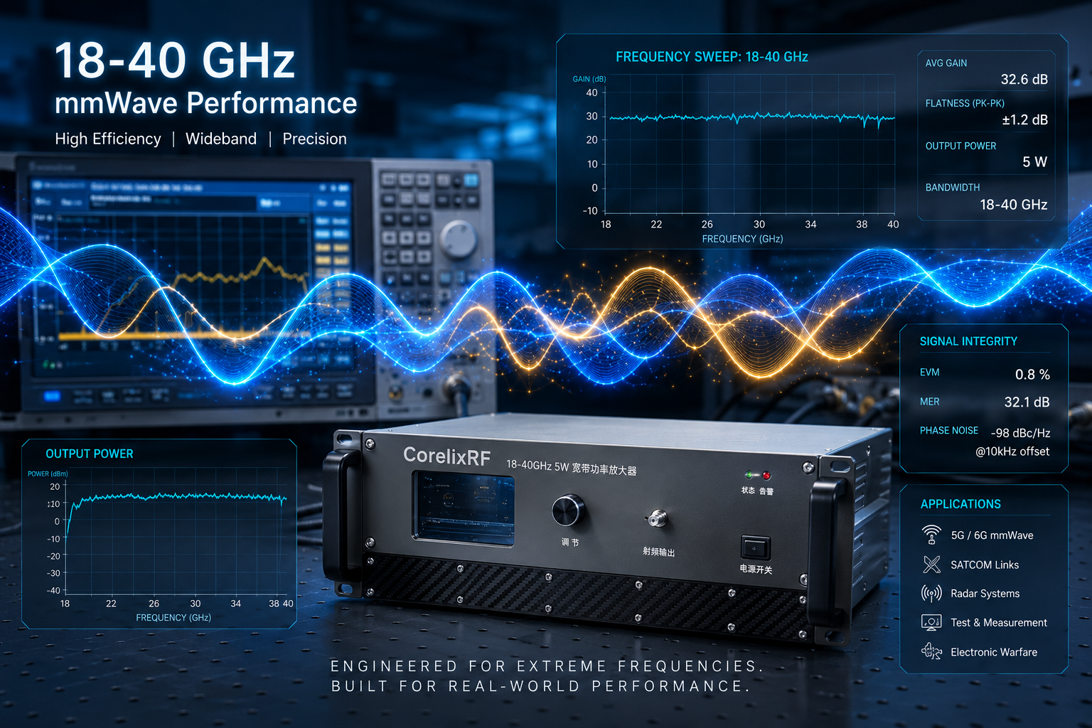
Many 18-40 GHz projects do not need to begin with a medium-power or high-power rack amplifier. In early mmWave development, the first requirement is often a compact, measurable driver-stage amplifier that can validate source output, fixture loss, connector path, calibration method, and device-under-test behavior. The CRF-PA-18000M40000M-5W is CorelixRF’s 5W standard class in the 18-40 GHz RF power amplifier family, positioned for compact lab testing, low-power integration, and driver-stage validation.
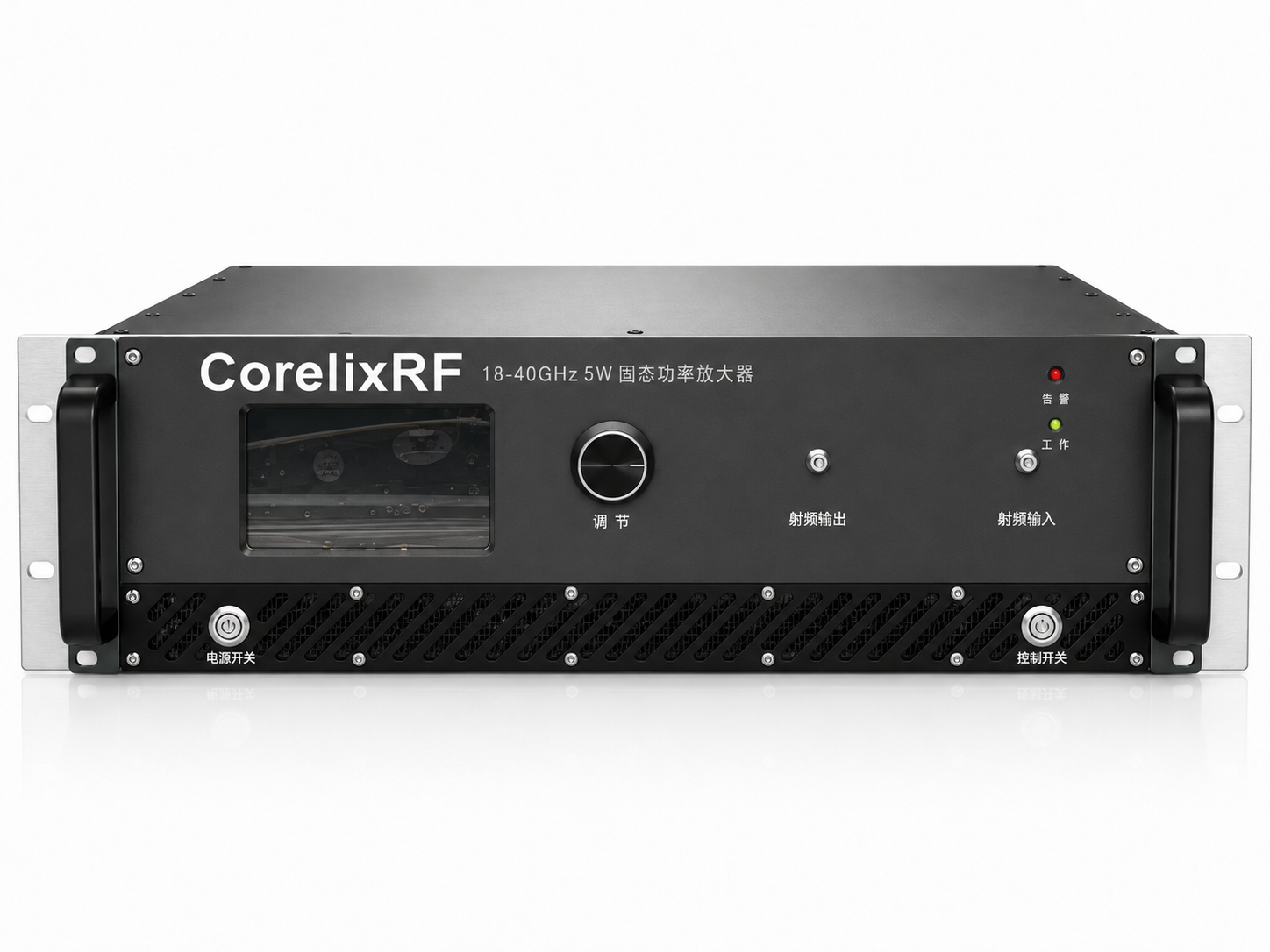
CorelixRF lists the CRF-PA-18000M40000M-5W with 18-40 GHz coverage, 5W output power, 37 dB gain, 2.92 mm-F RF output, and 19-inch 3U enclosure. This makes it a different selection problem from the higher-power 20W, 40W, and 70W classes in the same family. A lower-power 18-40 GHz RF amplifier can be the better fit when the bench is still being characterized and the team needs clean engineering data before scaling output power.
Quick Selection Snapshot
- Best-fit role: driver-stage validation, compact lab testing, low-power mmWave integration.
- Frequency class: 18-40 GHz, suitable for mmWave benches that need broad high-frequency coverage.
- Public output class: 5W, useful before committing to larger 20W, 40W, or 70W configurations.
- Interface note: 2.92 mm-F RF output is publicly listed for this model class.
- Selection warning: confirm output reference plane, fixture loss, and source drive before RFQ.
Why Start with the 5W Class
At mmWave frequencies, amplifier selection is strongly affected by connectors, adapters, cable loss, fixture repeatability, and measurement reference plane. A 5W class amplifier can help engineers validate the signal path without immediately adding the thermal, rack, and waveguide complexity of larger models. It is especially useful when the system is still evaluating whether final output needs to move to 20W, 40W, or 70W.
For SDR-driven or signal-generator-driven benches, the source output level across frequency should be measured before RFQ. The amplifier’s usable output depends on drive level, modulation, duty cycle, gain response, and any losses between the amplifier and the measurement point.
RFQ Details to Confirm
Before requesting the CRF-PA-18000M40000M-5W, define the exact operating window inside 18-40 GHz, required output at the final reference plane, input power range, waveform, duty cycle, test fixture loss, cooling environment, control interface needs, and documentation requirements. If the project requires a narrower frequency window, different interface, or custom enclosure, use CorelixRF’s custom RF amplifier review path.
When the amplifier is part of a complete source-to-load path, CorelixRF’s RF front-end platforms page is the right internal link for source, PA, filters, couplers, antenna/load, and control alignment.
How to Evaluate the Amplifier in a Real Bench
The most useful evaluation plan starts by defining the measurement plane. At 18-40 GHz, even short coaxial paths and adapters can create meaningful loss and uncertainty. If the team measures power directly at the amplifier output, the result may look very different from power measured after a cable, switch, attenuator, coupler, fixture, or device interface. For a fair review, document the entire path and decide where output power must be guaranteed or verified.
Engineers should also avoid testing only one frequency. A broadband mmWave amplifier may be used across many points inside 18-40 GHz, so the test plan should include low, middle, and high-frequency checkpoints that match the real application. If the amplifier is intended for a narrow portion of the band, use that operating window for the acceptance discussion. If the project needs full-band coverage, request swept gain and output behavior so the buyer does not assume flat performance from a single table entry.
Source Drive and Linearity Planning
A driver-stage amplifier is usually placed after a signal generator, frequency converter, SDR, or upconverter chain. The available input level may vary with frequency, and the waveform may have a crest factor that changes the relationship between average power and peak power. Before choosing the CRF-PA-18000M40000M-5W, record the source output level across the intended band and confirm whether the application needs saturated output, linear amplification, or controlled operation below compression.
This distinction is important for communication and modulation testing. If the project needs clean modulation quality, the amplifier may need to operate with output backoff. If the project only needs high-level CW or simple test output, the acceptance criteria may be different. CorelixRF should receive enough operating detail to recommend whether the 5W class is suitable or whether a higher-power model should be considered to create the required backoff margin.
Thermal and Mechanical Considerations
The public listing identifies a 19-inch 3U enclosure class for the 18-40 GHz family. Even when the output class is 5W, the rack environment still matters. Airflow direction, blocked vents, nearby heat sources, ambient temperature, and continuous run time can affect stability and repeatability. A bench that runs short manual tests has a different requirement from an automated station that runs long sequences over many hours.
Procurement teams should ask for the mechanical drawing early, especially when the amplifier must fit into an existing rack, shielded enclosure, or mobile test platform. Connector accessibility should also be checked. At mmWave frequencies, repeated connector mating, torque control, and cable strain relief can affect measurement consistency. If the final installation needs front-panel, rear-panel, or remote-control access, include that in the inquiry rather than treating it as a later detail.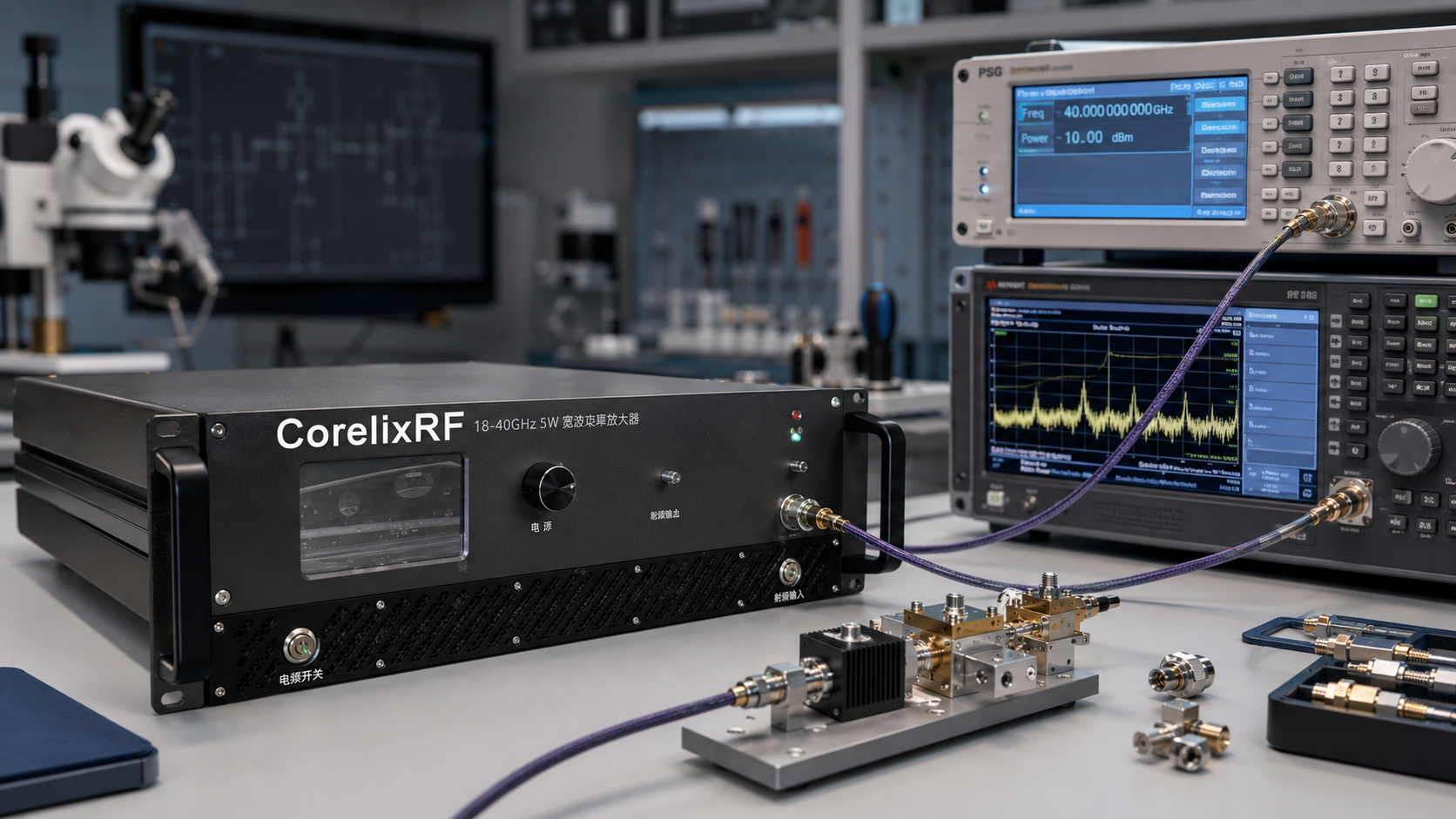
Documentation for Engineering Approval
For internal design review, the team should request the model datasheet, measured curves, interface information, operating notes, and any available factory test data. The goal is not only to confirm that the model exists. The goal is to decide whether the published 5W class can meet the real test conditions. If the project will be used by a customer, exported as part of an instrument, or repeated across multiple stations, documentation consistency becomes part of the purchase requirement.
A strong inquiry should describe the intended application without overstating it. For example, “18-40 GHz driver-stage validation for a signal-generator-based test bench” is more useful than a generic request for a mmWave amplifier. It gives CorelixRF a clearer path to review power, gain, connector interface, cooling, and data expectations.
FAQ
What is the CRF-PA-18000M40000M-5W?
It is CorelixRF’s 5W standard class in the 18-40 GHz CRF-PA-18000M40000M mmWave amplifier family.
What gain is listed?
CorelixRF lists 37 dB gain for the CRF-PA-18000M40000M-5W.
What RF output is listed?
The public table lists 2.92 mm-F RF output for this 5W model.
What is the best-fit use case?
CorelixRF lists compact lab testing, low-power integration, and driver-stage validation.
What should be included in the inquiry?
Include frequency window, output target, input drive, connector path, waveform, duty cycle, cooling, control, rack constraints, and data needs.