

This draft is a commissioning checklist. It assumes the 6-18 GHz amplifier has already been shortlisted and focuses on what must be verified before the rack is considered usable: reference plane, waveguide path, cooling, diagnostics, and acceptance data.
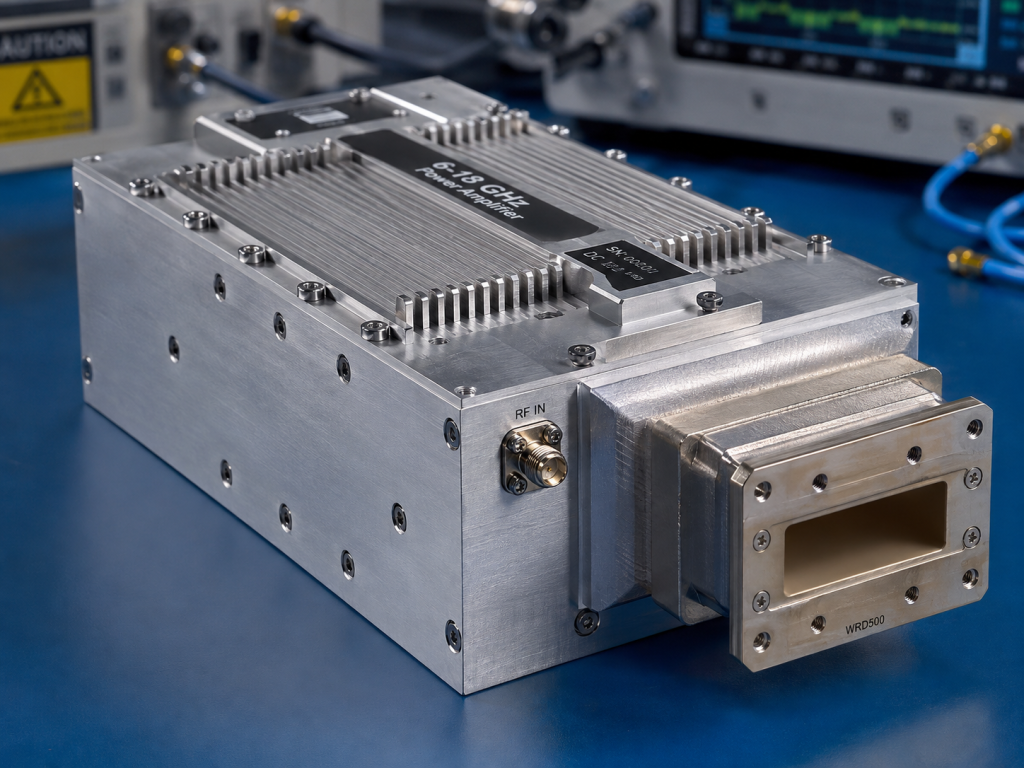
The checklist uses CorelixRF’s CRF-PA-6G18G-300W-M as the example platform. The local datasheet extraction lists 6 GHz to 18 GHz coverage, 300 W rated output power, GaN technology, 50 dB minimum small-signal gain, -5 to +5 dB gain flatness, SMA-F input and WRD500 output, forced-air cooling, and a 320 x 230 x 120 mm mechanical configuration.
Primary search phrase: 6-18 GHz microwave RF amplifier. Related long-tail phrases include microwave RF amplifier, 6-18 GHz amplifier, 300W GaN amplifier, solid state power amplifier, WRD500 amplifier.
Checklist Item 1: Define the Delivered Power Plane
A 300 W microwave amplifier is often purchased for a rack, antenna path, or fixture rather than a bare amplifier output. State whether 300 W is required at the amplifier connector, after the WRD path, after a coupler, or at the test fixture. The answer changes the gain and loss budget.
Commissioning check: write the power reference plane on the test sheet. A value measured before waveguide loss is not the same as delivered power at the fixture.
Checklist Item 2: Confirm the SMA-to-Waveguide Path
The datasheet lists SMA-F input and WRD500 output. That interface mix requires early decisions on waveguide run, bends, couplers, loads, and calibration adapters. At 6 GHz to 18 GHz, mechanical repeatability and connector discipline affect measured output power.
Commissioning check: inspect every transition before first drive. Waveguide routing mistakes are easier to prevent than diagnose at high power.
Checklist Item 3: Reserve Airflow and Service Space
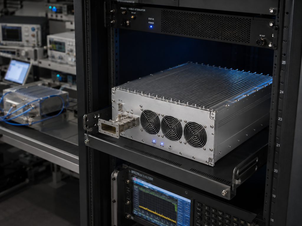
The unit uses forced-air cooling in a 320 x 230 x 120 mm mechanical configuration. Rack designers should reserve intake and exhaust clearance, keep hot exhaust away from other RF hardware, and allow access for output hardware inspection. Thermal behavior should be measured during a realistic sweep or dwell sequence.
Commissioning check: run the rack with covers, airflow, and neighboring equipment in their real positions. Open-bench thermal behavior can be misleading.
Checklist Item 4: Use Diagnostics in Automation
The project-ready control interfaces with temperature and current diagnostics should be part of the rack control plan. A test script should respond to alarms, log frequency and drive level, and put the source into a safe state when protection trips. Front-panel-only procedures are weak for repeatable microwave validation.
Commissioning check: confirm the control software can see alarm states and place the source in a safe condition.
Checklist Item 5: Ask for Data That Matches Use
A strong RFQ asks for gain, output power, thermal, and protection data at relevant points. If the waveform is swept, pulsed, modulated, or long-duration CW, the acceptance method should say so before quotation.
Commissioning check: ask for acceptance data that matches the intended use, not a generic best-case frequency point.
Rack Acceptance Sign-Off
Do not sign off the rack until the team has verified delivered power, output routing, airflow, alarm handling, and repeatable data capture. If any of those checks depends on a future adapter, later software change, or unverified cooling assumption, the RF amplifier is not fully integrated yet.
Commissioning Sequence
A clean commissioning sequence starts with mechanical inspection, then output termination, then low-level source verification, then amplifier enable, then stepped power increase. At each step, record the frequency, drive level, measured output, temperature, current, and alarm state. Do not jump directly to full power after a cable change or waveguide change. The 6-18 GHz band can involve several pieces of output hardware, and a small routing mistake can change measured power or reflected power. When the rack is automated, the commissioning sequence should also prove that the control software can stop drive and log the reason when an alarm appears. The final sign-off should include the exact output hardware used during acceptance, because future substitutions can change loss, match, and calibration confidence.
What Procurement Should Ask Engineering
Procurement should not ask only for price and delivery. Ask engineering whether the system needs full 6-18 GHz coverage or selected bands, whether the output is measured at the WRD500 interface or after downstream hardware, what duty profile will be used, and whether control data must be available to software. Those answers determine whether the quoted amplifier is a standard microwave block or part of a larger custom rack review. Also ask who owns the final test report, because the same amplifier may be used by design engineering, validation, and production groups with different evidence needs.
Related CorelixRF Resources
For readers comparing adjacent platforms, review 6-18 GHz RF power amplifier, microwave RF amplifier, RF testing and validation, custom RF development, and Contact CorelixRF. These links keep the next step inside the CorelixRF site and help buyers move from amplifier selection to a specific engineering review without relying on competitor pages or generic catalog assumptions.
FAQ
Why use a checklist format?
A 6-18 GHz 300 W microwave amplifier has several integration points that are easy to miss unless they are verified one by one.
What is the focus keyword?
Use 6-18 GHz microwave RF amplifier as the focus keyword.
What connector path is listed?
The local datasheet extraction lists SMA-F input and WRD500 output.
What should be verified before operation?
Verify delivered power reference plane, waveguide routing, airflow, control interface, alarm response, and load condition.