
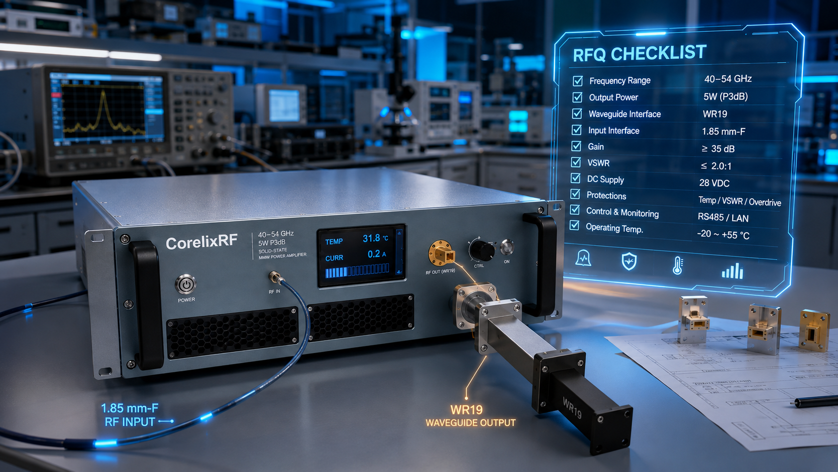
Use this article as an RFQ worksheet, not a general product overview. The CRF-PA-40000M54000M-6W, identified in the local specification file as CRF-PA40G54G-6W, is described as a GaN solid-state mmWave power amplifier covering 40-54 GHz with 6 W rated output power, 38 dB minimum small-signal gain, 1.85 mm-F input, WR19 output, forced-air cooling, real-time temperature and current monitoring, alarm protection, and a 19-inch 3U form factor.
The buyer searching for a millimeter-wave RF power amplifier at 40-54 GHz usually already has a bench, source, fixture, or waveguide path in mind. The RFQ should therefore answer practical questions before asking for price.
RFQ Question 1: Which Part of 40-54 GHz Matters?
Write the exact operating frequencies first. Full-band swept work is different from a fixed-channel validation setup. Include frequency points, step size, dwell time, waveform or CW mode, and the required output reference plane. If the full range is required, say so. If only selected windows matter, list them and avoid turning a narrow requirement into a vague wideband request.
RFQ Question 2: Where Is 6 W Required?
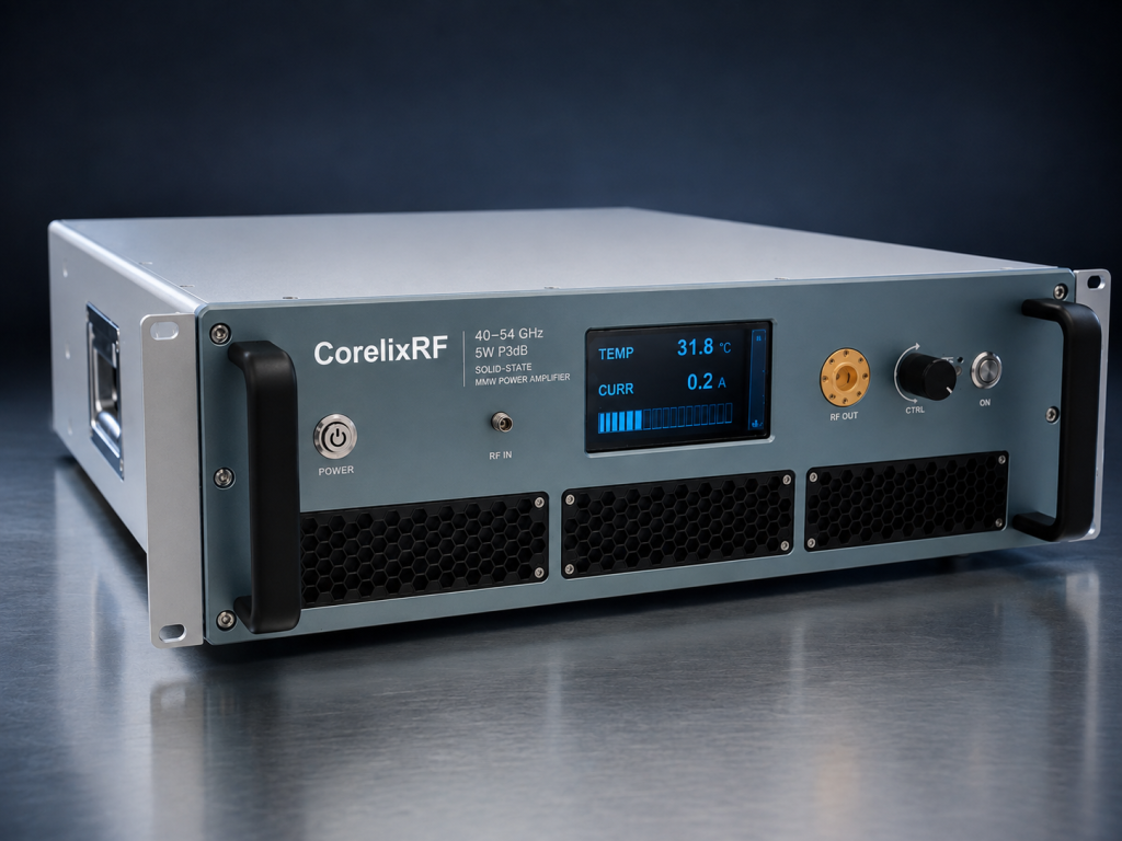
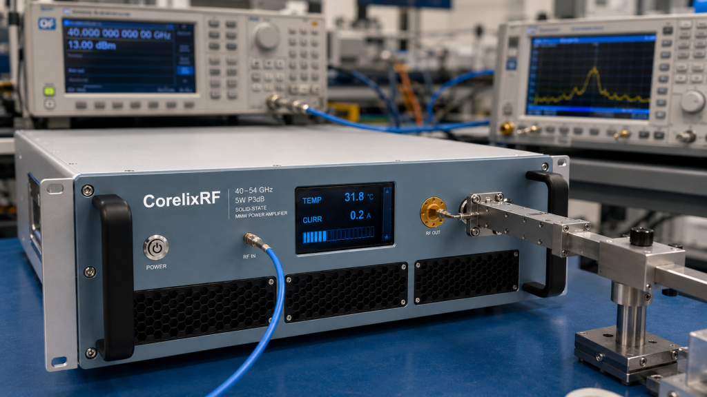
The source data lists WR19 output and 1.85 mm-F input. At this frequency, the phrase 6 W is incomplete unless the measurement plane is defined. Is the power required at the amplifier flange, after a coupler, after a waveguide bend, or at a DUT input? Name the transition, coupler, load, antenna, or fixture between the amplifier and the measurement point.
RFQ Question 3: What Source Drive Can Be Guaranteed?
The 38 dB minimum small-signal gain reduces source burden, but it also makes source discipline important. State the source maximum output, fixed attenuation, enable sequence, software limits, and whether the operator can change settings manually. A 40-54 GHz WR19 mmWave amplifier should not be commissioned with an undocumented startup routine.
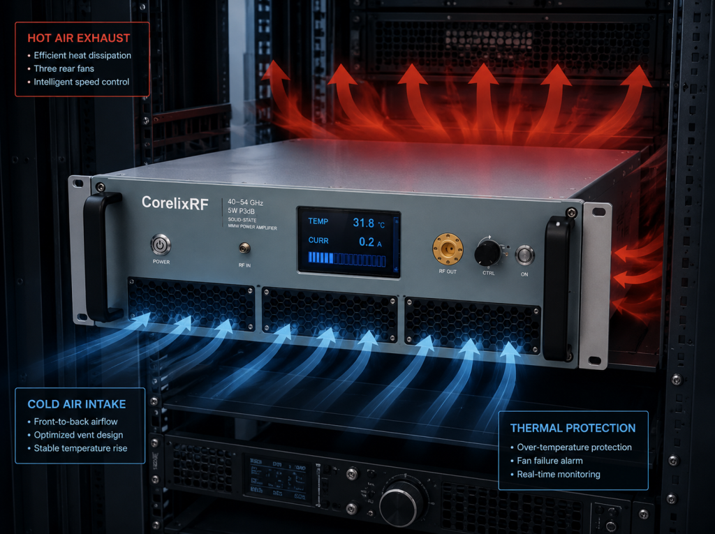
RFQ Question 4: Can the Rack Support the 3U Air-Cooled Unit?
The datasheet describes forced-air cooling and a 19-inch 3U form factor. Reserve intake and exhaust clearance, waveguide service access, and space for the 1.85 mm input connection. If the unit shares a rack with other hot instruments, request thermal review under realistic operating time rather than relying on an open-bench power check.
RFQ Question 5: What Evidence Should Be Supplied?
Ask which final documents can be supplied for project review: datasheet revision, outline drawing, test data, control protocol if applicable, and alarm behavior notes. For high-frequency systems, CorelixRF high-frequency RF capability is the right internal topic because the amplifier is part of a wider measurement chain.
RFQ Question 6: Is Standard Configuration Enough?
Use the standard path when WR19 output, 1.85 mm input, 3U packaging, forced-air cooling, and monitoring match the system. Use custom RF development when the project needs nonstandard enclosure limits, a special control interface, integrated source hardware, or a project-specific acceptance package.
RFQ Scorecard
Mark each item before sending the inquiry: operating frequencies documented; output reference plane named; WR19 path described; source drive limited; load or antenna identified; rack airflow checked; monitoring needs listed; alarm response defined; factory data requested. If any line is blank, the RFQ is not ready. CorelixRF RF testing and validation resources can help frame the evidence expected in the final review.
Red Flags Before Submission
Do not send the inquiry if the output requirement is written only as “6 W” without a reference plane. Do not send it if the source output can exceed the planned drive level and no attenuation or software limit is defined. Do not send it if the WR19 path is still changing but the quotation asks for final acceptance data. These are not paperwork details; they directly affect whether the amplifier can be reviewed against the real system.
A second red flag is a cooling assumption copied from another rack. The 3U forced-air package needs clear air movement in the actual installation, not only on a lab table. If the final system has a door, filters, nearby heat sources, or rigid waveguide runs, include those constraints. The supplier can only evaluate what is disclosed.
What a Complete Answer Looks Like
A complete RFQ answer might read: “We need 40-54 GHz coverage at three operating windows, CW operation, output measured at the amplifier WR19 flange, 1.85 mm source input, fixed WR19 load for acceptance, 19-inch rack installation with front service access, and data for output power, gain state, current, temperature, and alarm behavior.” That sentence is much more useful than a generic request for a Q-band amplifier.
Before sending, add whether the amplifier will be used by one engineering group or shared across several teams. Shared equipment needs clearer limits for source level, waveguide changes, and load verification.
FAQ
What frequency range is listed for this amplifier?
The local source specification lists 40-54 GHz.
What output power is specified?
The datasheet describes 6 W rated output power.
What RF interfaces should be planned?
The source data lists 1.85 mm-F input and WR19 output.
What should be included in the RFQ?
Include operating frequencies, output reference plane, waveguide path, source drive, load or antenna, rack cooling, control needs, monitoring, and acceptance data.