
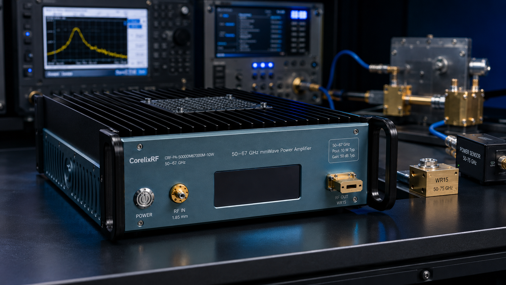
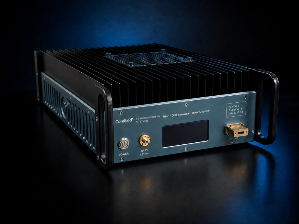
This article is written as an acceptance test plan. The CRF-PA-50000M67000M-10W, identified by the local datasheet file as CRF-PA50G67G-10W, is specified as a GaN solid-state mmWave power amplifier with 50-67 GHz frequency coverage, 10 W rated output power, 40 dB minimum small-signal gain, 1.85 mm-F input, WR15 output, 15 dB gain control range, forced-air cooling, real-time temperature/current monitoring, alarm protection, and a 19-inch 3U form factor.
The goal is to verify whether the mmWave power amplifier fits a real validation bench. The plan below assumes the buyer needs repeatable measurements rather than a single screenshot of output power.
Test Scope
Define the use case before connecting hardware. The amplifier may support test and measurement instrumentation, communication subsystem validation, RF interference system-level evaluation, or aerospace control work. Each case has a different operating time, waveform, source behavior, and downstream load condition. The test scope should list the exact frequencies inside 50-67 GHz and identify whether the full range or only selected channels must be accepted.
Required Equipment Record
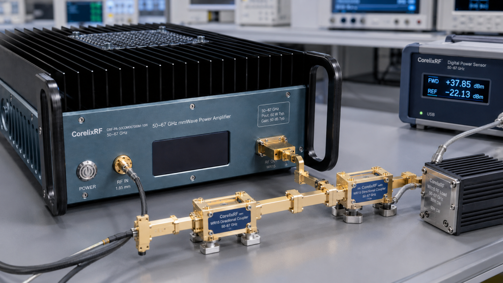
Record the source, frequency extender if used, 1.85 mm input transition, WR15 waveguide sections, couplers, bends, load, antenna, fixture, and power sensor. At 50-67 GHz, a test report without a hardware record is hard to reproduce. If the amplifier is part of a larger chain, CorelixRF RF front-end platforms are a relevant review path because source, amplifier, and output hardware interact.
Procedure A: Drive-Level Safety
Set the source to a known safe startup state. Add fixed attenuation if the source can exceed the intended drive level. Record gain state, source level, output reference plane, and enable sequence. The listed 40 dB minimum gain is useful, but it makes undocumented startup behavior a risk. No automated sweep should start until source limits are confirmed.
Procedure B: Output and Gain Verification
Measure output at the agreed reference plane. Log frequency, source level, gain setting, measured output, current, temperature, and alarm state. If the 15 dB gain control range is used, record at least the normal operating setting and one reduced-gain setting. The purpose is not to create a catalog table; it is to prove that the selected operating recipe is repeatable.
Procedure C: Thermal Hold
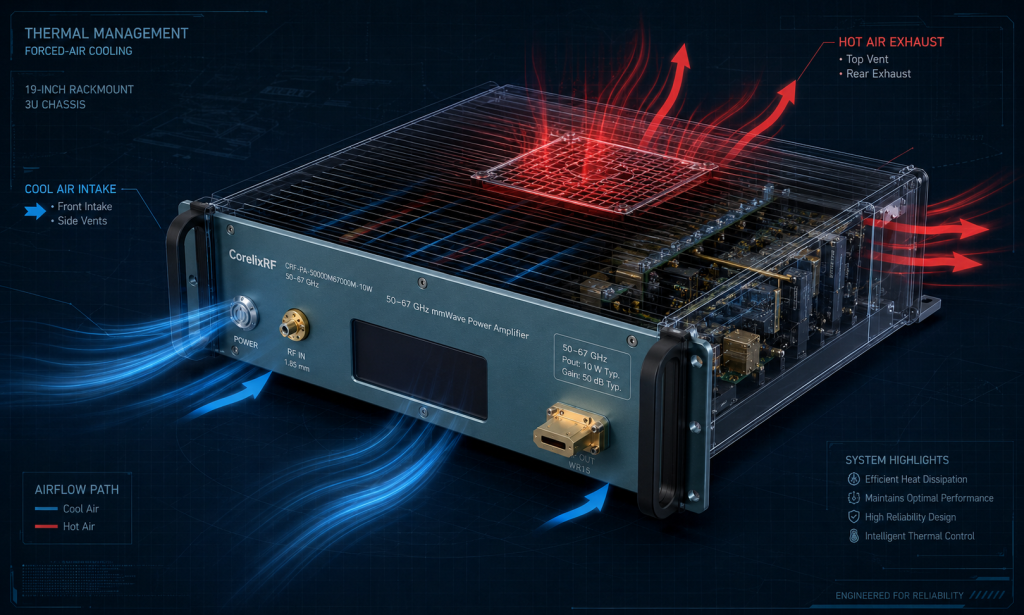
Run the amplifier long enough to represent the intended duty condition. The source data lists forced-air cooling in a 19-inch 3U package, so rack airflow matters. Record inlet conditions if available, keep intake and exhaust paths clear, and avoid testing in an open bench if the final system will be enclosed. CorelixRF RF testing and validation content aligns with this measured-evidence approach.
Procedure D: Alarm and Recovery Review
Protection features should be treated as system feedback. Define what the source does after an alarm, who resets the amplifier, and what event data is saved. A poor load or damaged WR15 transition can cause misleading behavior. Include load verification in the procedure before blaming the amplifier.
Pass/Clarify Decision
Pass the configuration when the agreed frequencies, reference plane, output target, thermal profile, gain settings, monitoring, and alarm behavior are documented. Clarify the requirement when the load is unknown, the source limit is not controlled, the WR15 path is not final, or the data package is not enough for internal approval. If standard hardware does not match the plan, request custom RF amplifier review.
Data Sheet for the Test Record
The test record should be built before the first run. Include columns for frequency, source setting, gain-control state, WR15 hardware used, measured output, current, temperature, alarm state, and operator note. If a value is estimated rather than measured, mark it as estimated. That small discipline prevents a common problem in mmWave validation: later teams trying to reproduce results without knowing which parts of the setup changed.
Failure Review Path
If the amplifier does not meet the target at one frequency, do not immediately classify the unit as failing. Check source power, waveguide alignment, load rating, sensor calibration, coupler loss, and gain state first. Then repeat the measurement at the same reference plane. A documented failure review protects both the buyer and supplier because it separates amplifier behavior from fixture and measurement problems.
Final Acceptance Package
The final package should include the accepted operating points, the setup record, output measurements, thermal log, alarm observations, and any unresolved clarifications. For purchasing teams, this package becomes the technical basis for approval. For engineers, it becomes the first operating recipe after the unit is installed.
If the acceptance package is intended for later audits, keep the raw measurement files with the summary. Screenshots alone are weak evidence. A short table with conditions, instruments, and file names is easier to trust when the setup is reviewed months later.
FAQ
What frequency range is listed?
The source datasheet lists 50-67 GHz.
What output power is specified?
The datasheet lists 10 W rated output power.
What interfaces are listed?
The source data lists 1.85 mm-F input and WR15 output.
What should be measured during acceptance?
Measure output power at a defined reference plane and log frequency, source level, gain state, current, temperature, alarm state, and load condition.