
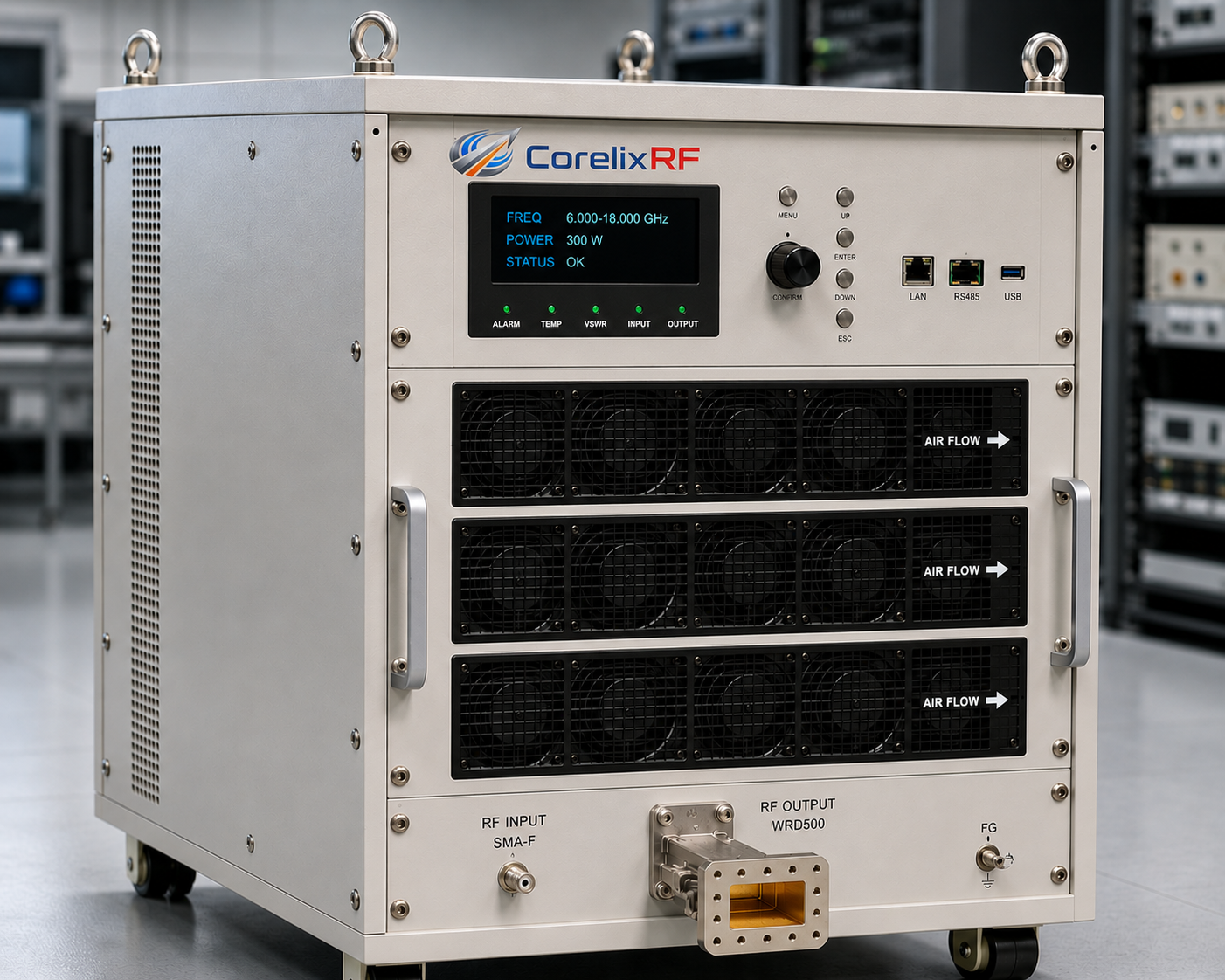
An 8-18 GHz RF test station is usually built for more than one simple power measurement. Engineers may need to validate microwave transmit chains, compare devices under test, run swept-frequency checks, verify antenna paths, evaluate broadband front-end behavior, or prepare a repeatable rack-level test process. In this frequency range, the amplifier is important, but it is only one part of the station. The signal source, driver path, power amplifier, output interface, couplers, load, sensors, cooling, control software, and documentation workflow all affect whether the test result is useful.
CorelixRF’s published 6-18 GHz GaN RF amplifier platform gives a practical baseline for an 8-18 GHz RF test station because it covers the upper C-band, X-band, and Ku-band-related range used by many microwave benches. Instead of treating the amplifier as a loose component, this article explains how to think about the complete test station: frequency coverage, output power class, connector or waveguide path, test scenarios, RFQ data, internal links, and the questions engineers should answer before requesting a configuration review.
The focus here is not to replace a 6-18 GHz GaN RF amplifier product page. A product page helps buyers compare model classes. A test-station article helps engineers plan how those models may be used in a real bench or rack system. That distinction matters for SEO and for engineering accuracy.
What an 8-18 GHz RF Test Station Needs to Do
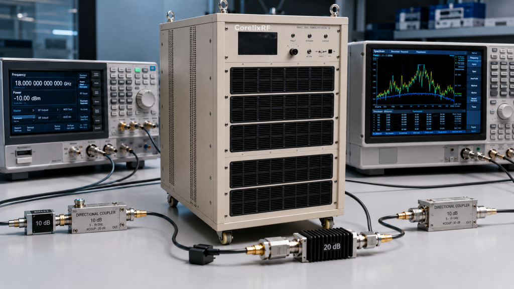
A useful 8-18 GHz RF test station should create a controlled RF path from source to measurement point. The station may start with a microwave signal generator, SDR/upconverter chain, synthesizer, or customer-defined RF source. That source then drives one or more gain stages, including a GaN power amplifier when higher output is required. Downstream components may include filters, directional couplers, attenuators, switches, sensors, dummy loads, antennas, or the device under test.
The station must answer several questions repeatably. Can the chain deliver usable RF output across the required 8-18 GHz window? Is output power stable enough at the test reference plane? Does the amplifier have enough gain for the available source drive? Are the coupler, load, cables, and waveguide components rated for the selected power class? Can the operator control the amplifier safely through RS485, LAN, or another project-defined interface? Can the station generate documentation that engineering and purchasing teams can use?
Why 8-18 GHz Is a Practical Test Window
The 8-18 GHz range is narrower than full 6-18 GHz coverage but still broad enough to create real integration challenges. Many benches do not need to test down to 6 GHz, yet they still need a strong microwave platform that covers X-band and upper microwave test points. By defining the station as 8-18 GHz, the engineering team can avoid over-focusing on a product-page keyword while keeping the system grounded in a real CorelixRF amplifier family.
This narrower test window may also help the RFQ. If the project only needs 8-18 GHz, state that clearly. CorelixRF can review whether a standard 6-18 GHz RF power amplifier configuration is suitable or whether a focused frequency review would be more appropriate. The goal is not to claim custom performance without review. The goal is to give the supplier the correct operating window before model selection.
CorelixRF Product Data to Use in an 8-18 GHz Test Station Article
The article should not invent model names, output classes, connector types, or waveguide interfaces. For an 8-18 GHz RF test station page, the safest product-based approach is to describe the information CorelixRF can confirm from its own product data and inquiry process: frequency range, rated output power, gain, input power range, RF input and output interface, cooling method, protection functions, control interface, mechanical format, and available test documentation.
If a specific CorelixRF amplifier model is available for 8-18 GHz operation, the model number and parameters should be inserted from the actual product specification sheet before publishing. If the project is handled as a custom or application-reviewed configuration, the article should say that CorelixRF can review the required 8-18 GHz test station conditions instead of presenting unverified model classes.
Specification Table for the Actual Product Page or Datasheet
| Specification Item | What to Fill from CorelixRF Product Data | Why It Matters in an 8-18 GHz Test Station |
|---|---|---|
| Frequency range | Confirmed operating band, such as 8-18 GHz or the exact supported range from the datasheet | Defines whether the station can cover the required microwave test window |
| Output power | Rated output power from the actual product specification | Determines whether the station can overcome cable, coupler, fixture, and DUT path losses |
| Gain | Datasheet gain value or measured gain range | Shows whether the available RF source can drive the station to the required output level |
| RF interfaces | Actual input and output connector or waveguide information | Affects cable selection, calibration plane, adapter loss, and rack layout |
| Cooling method | Actual cooling design from the product data | Supports stable operation during swept, repeated, or automated testing |
| Protection and control | Confirmed protection functions and control interface | Helps operators manage reflected power, faults, enable logic, and safe test operation |
| Test documentation | Available curves, test report, datasheet, or acceptance data | Gives engineers and buyers evidence for qualification and purchase approval |
This table is designed to be filled with actual CorelixRF product data before publication. It avoids claiming products or parameters that are not present in the company’s specification sheets.
Application Diagram for an 8-18 GHz RF Test Station
RF Source / Upconverter
        |
        v
Driver or Leveling Stage
        |
        v
CorelixRF GaN Power Amplifier
        |
        v
Directional Coupler ----> Power Sensor / Spectrum Analyzer
        |
        v
Filter / Attenuator / Switch Path
        |
        v
Dummy Load / Antenna / DUT
        |
        v
Test Report, Curves, Pass-Fail Notes
This diagram is intentionally simple. A real station may add interlocks, temperature monitoring, forward and reflected power readback, RF switching, calibration ports, software automation, or shielded test fixtures. The important point is that the amplifier should be selected after the whole path is mapped, not before.
Testing Scenario 1: Broadband Output Verification
In a broadband output verification station, the goal is to confirm usable output across the 8-18 GHz window. The operator may test at several fixed points, such as low, middle, and high-frequency checkpoints, or run a swept-frequency sequence. The station should define the measurement reference plane before testing begins. Power measured at the amplifier output will not be the same as power measured after cables, couplers, adapters, or fixtures.
For this scenario, request gain and output behavior across the actual test range. If the station must record repeatable data for internal qualification, ask CorelixRF about datasheets, measured curves, and unit-level test records. The RFQ should also describe whether the test is CW, pulsed, swept, modulated, or duty-cycle limited.
Testing Scenario 2: DUT Stress and Functional Testing
Some 8-18 GHz stations are built to expose a device under test to defined RF levels. In this case, the station must protect both the amplifier and the DUT. The coupler plan, attenuator rating, load condition, and reflected-power behavior should be reviewed before amplifier selection. If the DUT input is sensitive, the station may need step attenuation, software limits, interlocks, or a controlled ramp-up sequence.
The amplifier should be sized by required power at the DUT plane, not by an abstract output number. Fixture insertion loss and cable loss can be significant at microwave frequencies. If the DUT must receive a defined level, include those losses in the RFQ.
Testing Scenario 3: Antenna or Load Path Validation
An 8-18 GHz station may also be used to validate antenna feeds, dummy loads, or output-side RF paths. This is where mismatch and power handling become more important. The station should document the antenna or load VSWR expectation, cable rating, waveguide rating, coupler rating, and safe operating procedures.
For projects that include the amplifier plus antenna or load path, CorelixRF’s RF front-end platforms page is the right internal reference. It describes the amplifier, signal source, antenna/load/DUT, connector, control, cooling, and project-adjustment path as a matched RF chain instead of unrelated parts.
Testing Scenario 4: Rack-Level Automated Station
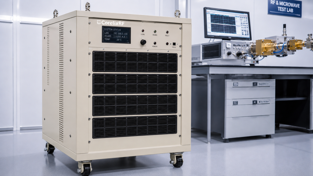
Automated stations need more than RF output. They need control timing, fault handling, measurement logging, repeatable calibration, operator safety, and service access. If the amplifier uses LAN or RS485 control, define how the control software will enable RF output, monitor status, log alarms, and coordinate with the signal source and measurement instruments.
For rack-level builds, confirm airflow direction, rack depth, power entry, grounding, cable routing, and maintenance access. Higher-power microwave amplifiers may require waveguide routing and output loads that are not easy to reposition after the rack is built. Mechanical planning should happen before the purchase order, not after delivery.
RFQ Checklist for an 8-18 GHz RF Test Station
- Exact frequency window: full 8-18 GHz or narrower sub-bands.
- Required output power at the amplifier output and at the final test reference plane.
- RF source type, available input drive, waveform, modulation, and duty cycle.
- Expected test mode: CW, swept, pulsed, modulated, automated, or manual.
- Connector or waveguide path, including adapters, cables, couplers, filters, switches, and loads.
- DUT, antenna, or load VSWR and power-handling expectations.
- Cooling method, rack space, airflow direction, and ambient temperature.
- Control interface requirements, such as LAN, RS485, interlock, alarms, or remote enable.
- Required documentation: datasheet, mechanical drawing, curves, factory test record, or acceptance criteria.
- Project stage, quantity, timeline, and whether the station is for prototype, lab, OEM, or production testing.
How to Avoid Over-Specifying the Amplifier
A common mistake is to choose the highest available power class before the station requirement is fully defined. Higher output may look attractive, but it increases cost, cooling requirements, RF safety concerns, load requirements, waveguide complexity, and rack integration work. If the station only needs source boosting or moderate DUT testing, a compact or mid-power model may be more practical.
Another mistake is to request full 6-18 GHz performance when the station only needs 8-18 GHz. A narrower requirement may simplify the review and help CorelixRF recommend the most suitable standard or adjusted platform. The RFQ should state what the station actually needs, not the broadest possible version of the requirement.
Internal Links for WordPress Placement
When this article is pasted into WordPress, keep the anchor text natural. Link to the most accurate CorelixRF product page only if the page represents the actual product being discussed. Link RF front-end platforms when discussing source, amplifier, antenna/load, and DUT matching. Link custom RF amplifier when discussing non-standard frequency, interface, cooling, or rack requirements. The CTA should point to CorelixRF Contact.
FAQ
What is an 8-18 GHz RF test station?
It is a microwave test setup that creates a controlled RF path across 8-18 GHz, usually including a signal source, amplifier, coupler, sensors, load, antenna, or device under test. The station is designed for repeatable measurement, validation, or system-level RF testing.
Can CorelixRF support an 8-18 GHz RF test station?
CorelixRF can review the required 8-18 GHz test station conditions against its actual product data or a custom RF amplifier path. The final model should be selected by confirmed frequency range, output power, gain, interface, cooling, control, duty cycle, and measurement requirements.
Should the station use connectorized or waveguide-output amplifiers?
That should be decided from the actual CorelixRF product specification and the station architecture. Do not assume an interface type before confirming the product data, output power, load path, coupler plan, and cooling requirements.
What information should be sent to CorelixRF for review?
Send the frequency range, required output power, signal source level, waveform, test mode, duty cycle, connector or waveguide path, load or DUT condition, cooling method, control needs, documentation requirements, quantity, and project stage.
How does this article avoid competing with the 6-18 GHz product page?
The article targets the application keyword “8-18 GHz RF test station” and focuses on bench architecture, testing scenarios, RFQ workflow, and station integration. The 6-18 GHz product page remains the product comparison and model-selection destination.