
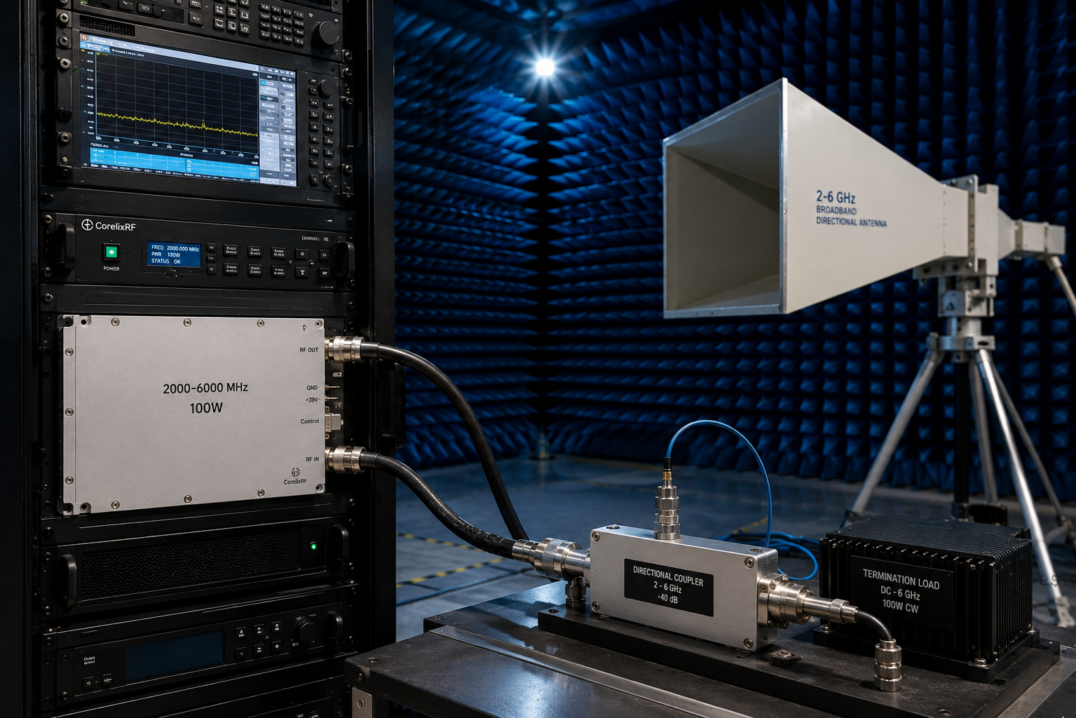
When an SDR source needs to move from signal generation into real RF output testing, the amplifier stage becomes one of the most important parts of the chain. A 2-6 GHz 100W RF power amplifier sits in a useful middle ground: it can support broadband S-band and lower C-band work, provide more output than a driver-stage module, and still remain practical for laboratory benches, OEM integration, communication test platforms, and controlled RF validation.
CorelixRF lists the CRF-PA-2G6G-100W as a standard model in the CRF-PA-2G6G series. The platform covers 2,000-6,000 MHz, provides 100 W output power, and lists typical gain of 49-51 dB. The public product page also identifies SMA input, N-female output, DB9 control, air cooling, and a 200 x 158 x 25 mm module size for the 100 W class. For teams comparing amplifier options, the useful question is not only whether the headline frequency and power match, but whether the RF chain, waveform, cooling path, control interface, and load condition are ready for that power level.
Why SDR Chains Need a Reviewed Amplifier Stage
SDR platforms are flexible because they can generate many waveforms and frequency plans from one hardware path. That flexibility also creates selection risk. A signal source may tune across a wide range, but the amplifier, cables, filters, attenuators, couplers, antenna, load, and measurement equipment must all be checked around the actual band and power target.
For a 2-6 GHz SDR output chain, the amplifier usually needs to answer five engineering questions: required output power, available input drive, duty mode, connector path, and thermal environment. The CorelixRF 2-6 GHz platform is positioned for RF test benches, SDR output chains, communication systems, and OEM integration. That makes it a useful starting point when the requirement needs broadband coverage instead of a narrow single-band PA.
If the project starts with the signal source, review CorelixRF’s SDR and RF front-end paths together with the RF power amplifier selection. For broader system matching, the RF front-end platform page is a practical internal link because it frames the chain as SDR source, RF amplifier, and output-side load or antenna.
Key Specification Points for CRF-PA-2G6G-100W
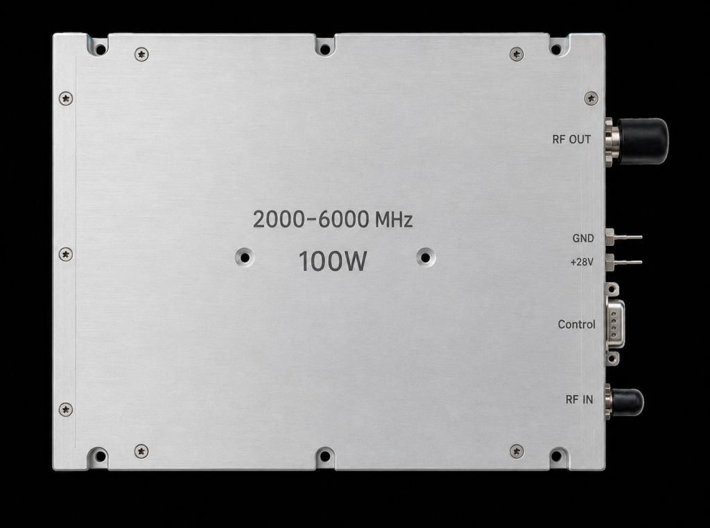
The CRF-PA-2G6G-100W is published as a 2,000-6,000 MHz, 100 W model with typical gain of 49-51 dB. It shares the listed 200 x 158 x 25 mm format used by several higher-power models in the same series. Publicly listed interfaces include SMA input, N-female output, DB9 control, and air cooling.
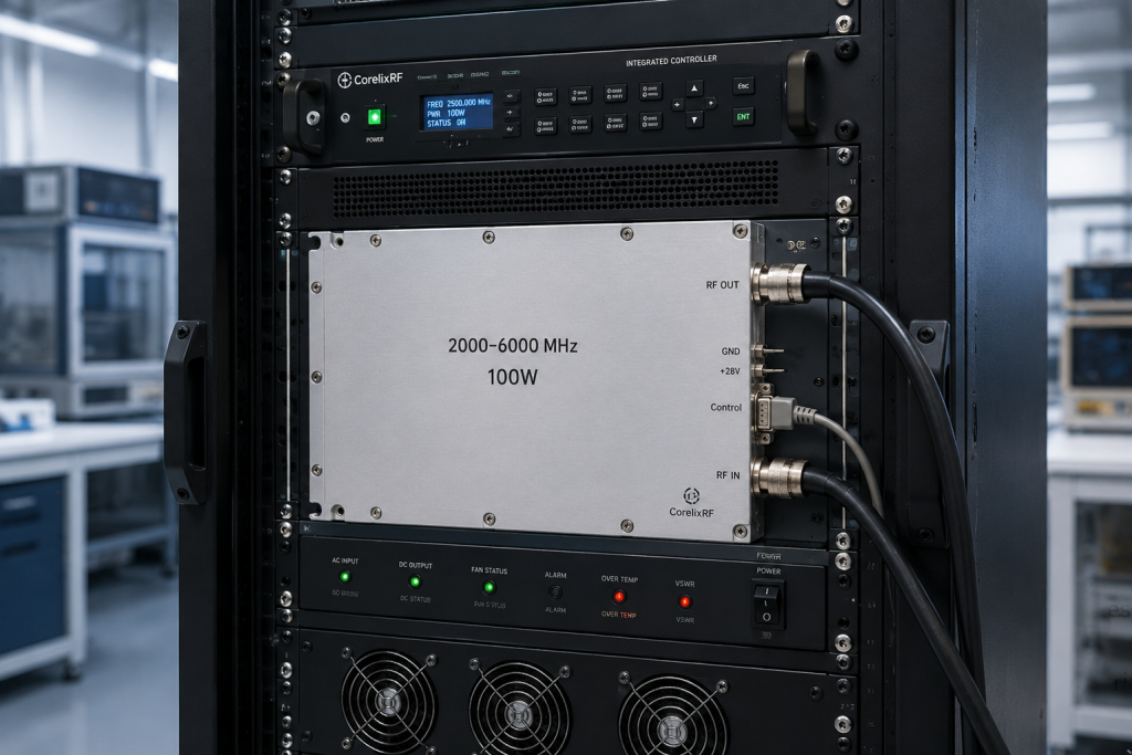
Those details matter during integration. SMA input is common for lab signal sources and RF driver paths, while N-female output is more suitable for a higher-power coaxial output connection than small precision connectors. DB9 control gives integrators a defined control interface to discuss during project review, especially when the amplifier needs to be embedded into a larger test rack or OEM subsystem.
Where a 2-6 GHz 100W Amplifier Fits Best
A 2-6 GHz 100W amplifier is commonly considered when the project needs more than a low-power driver but does not yet require cabinet-level kilowatt planning. Example use cases include SDR output chain validation, communication test paths, RF bench amplification, broadband device testing, and early system integration.
The output stage should still be treated carefully. At 100 W, cable loss, mismatch, coupler power rating, load power handling, and cooling airflow can all affect test reliability. Engineers should confirm that the load or antenna path is appropriate before applying full RF drive. If the setup involves an antenna rather than a lab load, the antenna gain, VSWR, cable route, and RF exposure plan should be reviewed before operation.
For buyers who are still narrowing the band, CorelixRF’s standard RF amplifier platforms provide a broader map from 30 MHz to 40 GHz. If the project falls below 2 GHz, the 300-2700 MHz RF power amplifier path may be a closer starting point. If the project needs higher microwave coverage, the 18-40 GHz RF power amplifier family shows how connector, waveguide, and rack decisions become more important at mmWave frequencies.
Selection Checklist Before RFQ
Before requesting a recommendation, prepare the actual operating band, target output power, input signal level, waveform type, duty cycle, connector preference, control requirement, cooling condition, and intended load. These details allow the engineering review to determine whether the CRF-PA-2G6G-100W is the right standard model or whether another 2-6 GHz power class is more suitable.
The 2-6 GHz family includes 30 W, 50 W, 100 W, 150 W, and 200 W standard classes. If the system only needs a compact driver stage, a lower-power model may be easier to integrate. If the path needs more margin, the 150 W or 200 W model may deserve review. The most reliable selection comes from matching the amplifier to the real RF chain, not simply choosing the largest available power class.
FAQ
What is the focus keyword for this article?
The focus keyword is 2-6 GHz 100W RF power amplifier.
Is the CRF-PA-2G6G-100W suitable for SDR output chains?
It is positioned as a 2-6 GHz broadband RF power amplifier option for SDR output chains, RF test benches, communication systems, and OEM integration. Final suitability depends on drive level, waveform, duty mode, load, and cooling.
What interfaces are publicly listed for the 2-6 GHz series?
CorelixRF lists SMA input, N-female output, DB9 control, and air cooling for the 2-6 GHz platform. Detailed supply, current, VSWR, harmonic, spurious, and mechanical data should be requested during engineering review.
When should a custom RF amplifier review be requested?
Request a custom RF amplifier review when the required frequency window, connector, control interface, mechanical format, cooling path, or documentation needs do not match the standard platform.
What information helps CorelixRF recommend the right model?
Share frequency range, output power, input drive, waveform, duty cycle, connector preference, load condition, supply requirements, cooling limits, quantity, and project stage.