
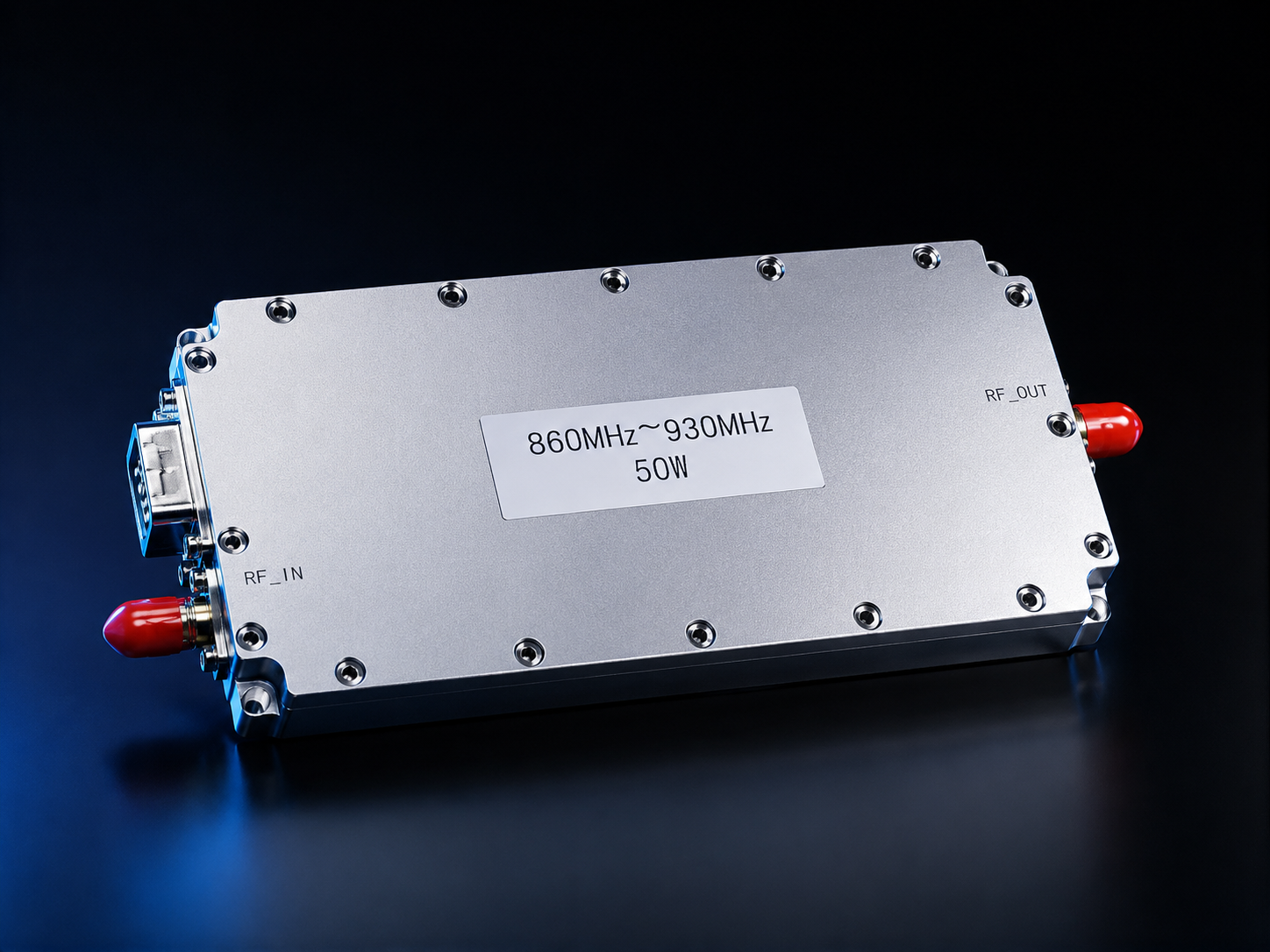
This runbook is for the first controlled bench session with the CorelixRF CRF-PA-860M930M-50W, an 860-930 MHz 50W narrowband RF power amplifier described in the local datasheet as a third-generation GaN SSPA module. The useful question is not only whether the module can meet the listed RF numbers. The better question is whether the lab, source, control line, heat path, and record sheet are ready before RF output is enabled.
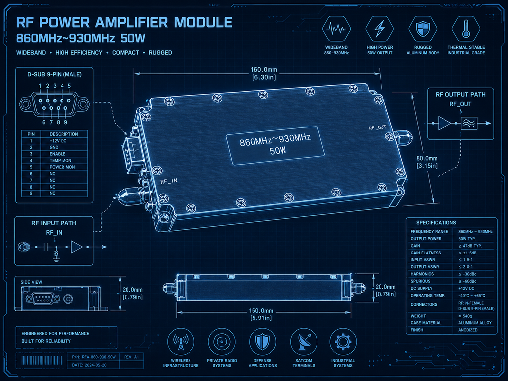
The datasheet lists 860 MHz to 930 MHz coverage, 40 W minimum and 50 W typical saturated output power, 43 dB minimum, 45 dB typical, and 47 dB maximum gain, an SMA-KFD46 RF interface, D-Sub 9-pin female power and control connectors, +24 V to +32 V supply with +28 V nominal, 5 A typical and 6 A maximum operating current, 125 x 59 x 21.5 mm mechanics, 0.5 kg weight, and external heat-sink cooling. It also describes an M version without internal VCO and a V version with internal VCO source and 10 Hz stepping.
Before Power Is Applied: Identify the Variant
Start by writing one line at the top of the bench sheet: M version or V version. For the M version, the RF source is external, so the source limit, cabling, frequency plan, and input level control belong to the lab setup. For the V version, the internal VCO source and scan function become part of the acceptance conversation. The V-version data includes 760 MHz to 1000 MHz frequency adjustment and 30 MHz to 180 MHz bandwidth adjustment, but the amplifier article should still keep the stated 860-930 MHz amplifier range clear.
This variant check is also the right moment to decide whether the module is a standalone RF front-end platform component or part of a project-specific assembly. If packaging, additional control, shielding, or a different mechanical handoff is expected, route the discussion to custom RF systems review before the bench plan becomes a purchase assumption.
Station Setup: Make Heat Visible First
Place the module on the planned external heat sink before output testing. The datasheet does not describe fan-only operation or a complete enclosure; it names external heat-sink cooling. The bring-up sheet should record mounting surface, thermal interface material, ambient condition, nearby heat sources, and whether airflow over the heat sink is present. Thermal notes belong before RF notes because shutdown above 80 C +/-5 C and automatic recovery below 70 C +/-5 C are part of the listed behavior.
After the heat path is installed, set the supply current limit and confirm the D-Sub wiring. Pins 1-4 are VDD, pins 5-7 are ground, pin 8 is PA_EN, and pin 9 is NC. PA on is 0 V or floating; PA off is 3.3 V or 5 V input. That PA_EN behavior should be shown on the drawing, not hidden in an email thread.
First RF Pass: One Frequency, One State
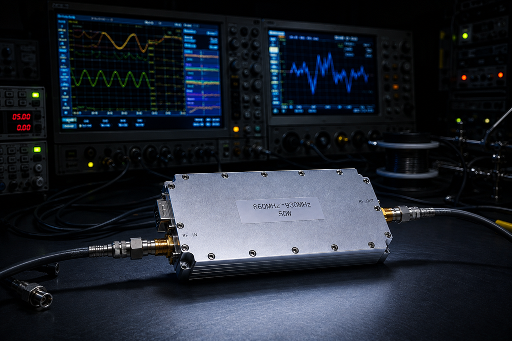
Do not begin with a wide sweep. Pick one documented frequency point inside 860-930 MHz, confirm the load and output reference plane, set the source low, then enable the PA. Log supply voltage, current, temperature, PA_EN state, input source condition, and measured output. This is where the phrase 50w rf amplifier should be used carefully: the datasheet supports 50 W typical saturated output power, but the article should not imply that every bench condition or every customer system will deliver that number without a defined test setup.
| Bring-up item | Record before moving on |
| Variant | M external source or V internal VCO source |
| Thermal path | Heat sink, interface material, ambient condition |
| Control line | D-Sub wiring and PA_EN state |
| RF path | Frequency, source setting, load, output reference plane |
| Evidence | Voltage, current, temperature, output reading, operator note |
Second RF Pass: Expand Only After the Record Is Stable
Once the first point is stable, add the remaining frequency points that matter to the project. A communication-system evaluation may care about a narrow channel plan. An RF test and measurement system may care about repeatable readings at several points. A project-specific RF source integration may care more about source ownership, enable timing, and recovery after a thermal event. This is the practical difference between a generic broadband RF amplifier discussion and a narrowband UHF module bring-up.
Use workbook terms only where they help the engineer search and verify the page. In this article, uhf rf amplifier, uhf rf power amplifier, radio frequency power amplifier, and sdr amplifier are attached to the setup problem: frequency control, source selection, PA enable, thermal hold points, and repeatable output evidence. They are not used as claims about a finished SDR radio or fielded communication product.
Real Bring-Up Application Scenarios
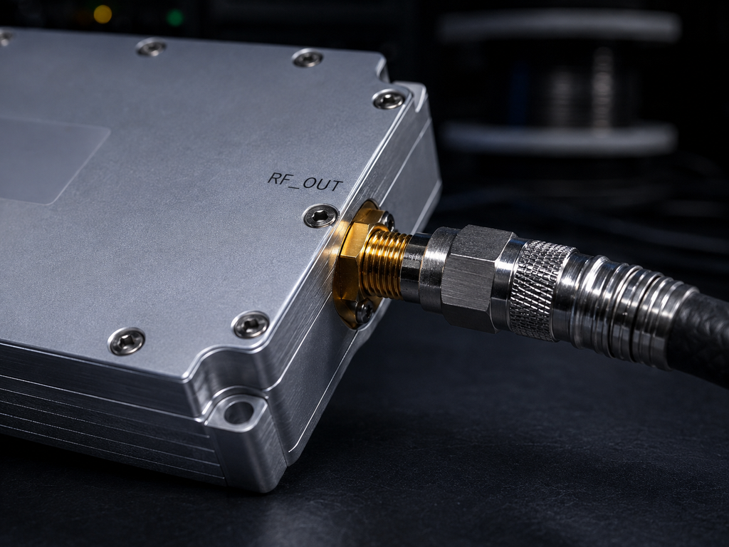
The real application categories named in the local datasheet are narrowband RF system amplification, communication systems, RF test and measurement systems, and project-specific RF source integration. The runbook format fits those categories because each one starts with the same operational question: what must be true before the PA is enabled?
For narrowband RF system amplification, verify the heat sink, channel plan, and output reference plane. For communication systems, keep the article in an engineering-evaluation context unless the final system is separately qualified. For RF test and measurement systems, document the source, load, and measurement method so readings are reproducible. For project-specific RF source integration, separate the M-version external-source plan from the V-version internal VCO source with 10 Hz stepping.
What to Send With the RFQ
A useful RFQ includes the target frequency points, M or V version preference, expected source architecture, supply plan, D-Sub control drawing, heat-sink concept, duty or test condition, output reference plane, required documents, and whether the buyer needs module-only delivery or additional integration support. The RF product finder can help compare nearby options, while engineering and manufacturing context is relevant when drawings, test data, and repeatable production documentation matter.
The boundary is simple: the datasheet supports the listed band, power class, gain range, GaN SSPA module description, M/V source options, D-Sub control, supply range, current range, heat-sink cooling, operating temperature, and thermal behavior. It does not support claims about inventory, customer deployments, certified field performance, or a complete radio system. Keep the public article close to the bring-up record, and the result reads like engineering support instead of template SEO copy.
FAQ
What frequency range does CRF-PA-860M930M-50W cover?
The local datasheet lists 860 MHz to 930 MHz coverage for the amplifier.
What output power and gain are listed?
The source lists 40 W minimum and 50 W typical saturated output power, with 43 dB minimum, 45 dB typical, and 47 dB maximum gain.
How are the M and V versions different?
The M version has no internal VCO. The V version includes an internal VCO source and scan function, with 10 Hz stepping listed in the local data.
What should be confirmed before first RF output?
Confirm the variant, heat sink, D-Sub wiring, PA_EN state, source condition, load, output reference plane, supply setting, current limit, and temperature record.