
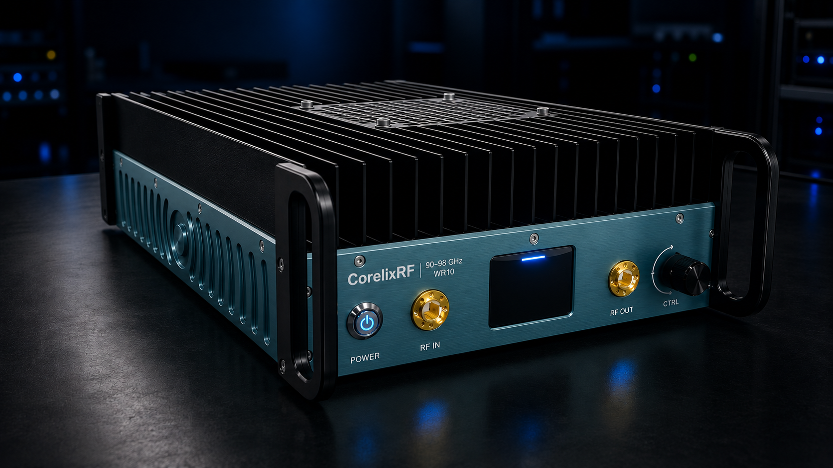
A 90-98 GHz 2W WR10 power amplifier is usually evaluated as part of a measurement chain, not as an isolated line item. The CorelixRF local datasheet identifies CRF-PA-90000M98000M-2W as a GaN SSPA covering 90 GHz to 98 GHz with 2 W saturated output power. It lists 40 dB minimum small-signal gain, +/-10 dB gain flatness, 15 dB gain control range, WR10 front-panel input and output, RS485 control, AC 220 V +/-10 percent 50/60 Hz supply, forced-air cooling, 0 to +50 C operation, and a small-unit mechanical format.
This notebook-style article follows the questions an RF engineer writes down while preparing a W-band bench. The source also lists 50 ohm / 2:1 typical input impedance or VSWR, -20 dBc typical harmonics, -60 dBc maximum spurious, real-time temperature monitoring, real-time current monitoring, optional forward/reverse power monitoring, alarm and fault protection, over-temperature protection, over-drive protection, over-voltage protection, and VSWR protection and alarm functions.
Notebook Entry: The WR10 Path Owns the Reading
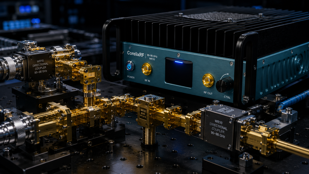
The first note should name the WR10 path before naming the pass/fail limit. At 90-98 GHz, a waveguide section, bend, transition, coupler, sensor, or load can change what the team believes the amplifier is doing. The record should state whether the reading is taken at the amplifier output flange or after another piece of waveguide hardware. If the amplifier is part of a larger RF integration project, the notebook should describe the full path instead of treating the amplifier body as the only boundary.
Notebook Entry: Gain Control Is a Test Condition
The 15 dB gain control range should not be left as background information. Write the gain-control state next to every frequency point, output reading, source setting, current value, and temperature value. That keeps rf amplifier gain from becoming a vague phrase. In a W-band notebook, gain is a recorded state that explains how the measurement was made.
The same discipline applies to power amplifier rf searches. A buyer may arrive with that broad phrase, but the article should narrow the question quickly: Which WR10 reference plane? Which source level? Which gain state? Which cooling condition? Which monitoring option? Those details make the page useful to an engineer instead of turning it into a generic broadband RF power amplifier overview.
Notebook Entry: Monitoring Changes the Evidence Package
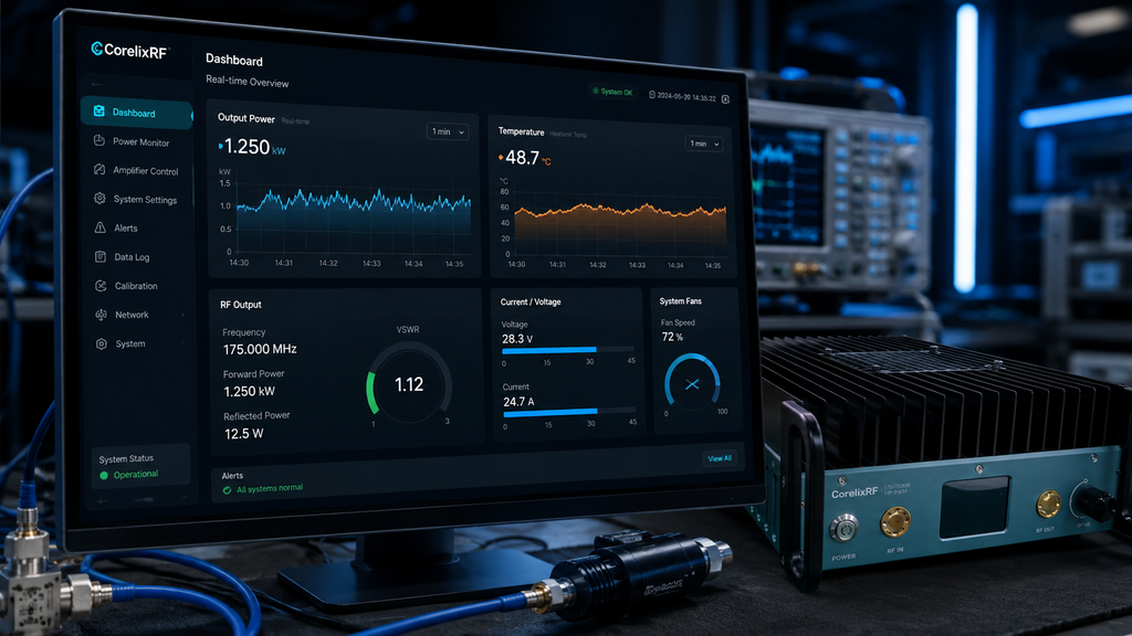
Temperature and current monitoring are listed in the datasheet. Forward/reverse power monitoring is described as optional. The notebook should therefore contain two possible evidence packages. A basic bench record can include source setting, gain state, WR10 path, measured output, current, temperature, and alarm status. A project that needs remote evidence should ask about the optional power monitoring before ordering, especially if the amplifier will be reviewed as part of custom RF systems.
| Notebook field | Why it matters |
| WR10 reference plane | Prevents mixed output-power claims |
| Gain-control state | Explains each power reading |
| Source level | Protects a high-gain W-band setup |
| Temperature and current | Creates baseline evidence for later comparison |
| Alarm status | Shows whether protection behavior affected the run |
Notebook Entry: Cooling Notes Belong Beside RF Notes
Forced-air cooling is part of the product description, so airflow should be visible in the acceptance record. Note the ambient condition, inlet clearance, exhaust direction, nearby heat sources, and mounting position. This is especially important for a high frequency power amplifier because later measurement differences may come from setup changes rather than a different amplifier response.
Real Measurement-Chain Application Scenarios
The local datasheet names the real application areas as test and measurement instrumentation, communication systems, RF interference system-level testing, and aerospace control systems. The notebook should keep those scenarios specific. For test and measurement instrumentation, document the source, sensor, load, and WR10 reference plane. For communication systems, frame the content as engineering evaluation unless the final system has its own qualification record.
For RF interference system-level testing, the wording should stay within authorized test environments and avoid claims about unverified field outcomes. For aerospace control systems, the article can discuss engineering setup, documentation, monitoring, and protection review, but it should not claim platform qualification or customer history. These boundaries keep the solid state power amplifier and rf power amplifier modules language tied to what the datasheet actually supports.
What the Buyer Should Attach
A serious inquiry should attach the frequency points, WR10 path drawing, expected source level range, gain-control needs, load and sensor method, cooling environment, monitoring requirement, document package requirement, and any control-interface expectation. The RF product finder can support early comparison, while engineering and manufacturing context matters when the team needs drawings, test data, and repeatable documentation.
The public claim boundary is equally important. The datasheet supports 90 GHz to 98 GHz coverage, 2 W saturated output power, 40 dB minimum gain, gain control, WR10 interfaces, RS485 control, AC supply, forced-air cooling, monitoring, alarms, and protection functions. It does not support claims about inventory, final system calibration, certified application outcomes, or named customer deployments. The safest article invites a technical review and asks the reader to share the real measurement chain.
FAQ
What frequency range does CRF-PA-90000M98000M-2W cover?
The local datasheet lists 90 GHz to 98 GHz coverage.
What output power and gain are listed?
The source lists 2 W saturated output power and 40 dB minimum small-signal gain.
What RF interfaces are listed?
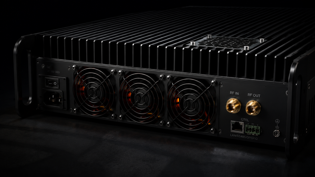
The datasheet lists WR10 front-panel input and output.
What monitoring and protection details are relevant?
The local data lists temperature and current monitoring, optional forward/reverse power monitoring, alarms, and protection for over-temperature, over-drive, over-voltage, and VSWR conditions.